Tag Archives: high bearing

China supplier The Best Cover Case Bearing Lh Rotavator Spare Parts Used for Dh246f Heavy Plus with high quality

Product Description

Product Description

Hello! My Friends! If you couldn’t find the products you need on our website, you can feel free to contact us, we will reply you as soon as possible. 


Company Profile
 

HangZhou CZPT Imp. & Exp. Co., Ltd. is a comprehensive firm integrating industrial manufacturing with international trade. Over a history of 32 years in business, it has developed a complete operation system, with a leading team of international trade and marketing professionals in the front, and a manufacturing team of high-end research and development technicians and rigid quality control specialists to extend back support. It has a product sample center and logistics warehouse of 3,000 square meters in area.

In order to put into full play its advantages of client and market resources, CZPT selects a number of qualified manufacturers as its reliable production workshops and possesses signed exclusive authority to export their products to overseas markets including Hong Kong, Macao and ZheJiang .

Luckystar has the capacity to manufacture, tailor-make and sell different categories of products covering a wide range of applications. Of all of its business scope, the main and advantaged supply is the following series products.

Agricultural machinery series:
We have developed on our own and manufacture exclusively a series of export-oriented rotary tillers, variable-speed paddy field stubble-bury beaters, foldable paddy field stubble-bury cultivators, and 1GD-350 type paddy field ridge shapers.

Luckystar is specialized in supplying series accessories supporting CZPT and CZPT combines, tractors and tillers among other world recognized brands. Specifically, the following types of spare parts are available in stock.

(1) Components for CZPT harvesters with specifications of DC60, DC68G, 688Q, DC70G, DC70H, DC70PLUS, DC95, and DC105.

(2) Spare parts for CZPT tractors, namely, gears, connecting rods, shafts, hydraulic pumps, clutches, and ball attachments. Relevant specifications cover L1500, L2201, L2202, L2402, L3408, L3608, L4508, L4708, L5018,M6040, M5000, M7040, M8540, M9540, M9000, M105,and M1304.

(3) Components for CZPT tillers with specifications of RX162, RX164, RX180, RX182, and RX220.

(4) Components for CZPT harvesters with specifications of AW70, AW82,AW85, YH700, YH850, and YH880. 

(5) Components for CZPT engines with specifications of D1403, D1503, D1703, V2203, V2403, V3300, V3307, and V3800.

Luckystar has in human resources highly competent talents including international business engineers, adheres to the business phylosophy of credibility, client-centricity and teamwork, and remains dedicated to provide clients with optimum commodities and quality service.

Luckystar highly values and consistently optimizes client service and has so far established long-term cooperation relations with many well-recognized corporations in the world. Our products are exported world wide to the USA, Europe, Japan and South Korea, and in particular, to Thailand, Vietnam, Indonesia, Malaysia, the Phillipines, Egypt, India, Sri Lanka, Myanmar and ZheJiang .

Your selection of us shall be a selection of professionalism.

Luckystar Imp. & Exp. Co., Ltd. cordially welcomes clients, associations and friends both at home and abroad to contact us for business cooperation and mutual benefit. We are looking forward to having you as our next business partner.


FAQ
 

1. Who are we?

We are based in ZheJiang , China, start from 2006,sell to South Asia(8.33%),Northern Europe(8.33%),Central America(8.33%),Western Europe(8.33%),Eastern Asia(8.33%),Mid East(8.33%),Oceania(8.33%),Africa(8.33%),Southeast Asia(8.33%),Eastern Europe(8.33%),South America(8.33%),North America(8.33%). There are total about 11-50 people in our office.

2.How can we guarantee quality?

Always a pre-production sample before mass production;
Always final Inspection before shipment;

3.What can you buy from us?

Various Agricultural Machinery and Spare Parts,Woodworking Machine,Construction Machinery,Oilfield Equipment & spare parts,Abrasive Cloth and Paper

4.Why should you buy from us not from other suppliers?

Our company was established in 2006. We are very professional in ensuring the high quality of products and services. The purpose of our company is to serve our customers wholeheartedly. Customer satisfaction is our grestest pursuit.

5.What services can we provide?

Accepted Delivery Terms: FOB,CFR,CIF;
Accepted Payment Currency:USD;
Accepted Payment Type: T/T;
Language Spoken:English,Chinese


Industrial applications of casing

For rotating and sliding parts, bushings are an important part of the machine. Due to their anti-friction properties and load-carrying capacity, they are an important part of many different industrial processes. Bushings play a vital role in industries such as construction, mining, hydropower, agriculture, transportation, food processing and material handling. To learn more about the benefits of bushings, read on. You’ll be amazed how much they can help your business!
bushing

type

When comparing enclosure types, consider the material and how it will be used. Oilite bushings are made of porous material that draws lubricant into the liner and releases it when pressure is applied. These are manufactured using a sintered or powered metal process. Copper and tin are the most commonly used materials for making copper bushings, but there are other types of metal bushings as well.
Another popular type is the plain bearing. This type reduces friction between the rotating shaft and the stationary support element. This type provides support and load bearing while relying on soft metal or plastic for lubrication. Journal bearings are used to support the linear motion of the engine crankshaft in large turbines. They are usually babbitt or hydrodynamic with a liquid film lubricant between the 2 halves.
The oil-impregnated paper sleeve is made of high-quality kraft insulating paper. These bushings contain 2 layers of capacitor grading, with the innermost layer electrically connected to the mounting flange. These are mature processes and are widely used in different voltage levels. CZPT Electric (Group) Co., Ltd. provides UHV DC and AC oil-impregnated paper wall bushings for environmental control rooms.
Electrical bushings are used to transmit electricity. These can be transformers, circuit breakers, shunt reactors and power capacitors. The bushing can be built into the bushing or through the bushing. The conductors must be able to carry the rated current without overheating the adjacent insulation. A typical bushing design has a conductor made of copper or aluminum with insulation on all other sides. If the bushing is used in a circuit, the insulation needs to be high enough to prevent any leakage paths.
Voltage and current ratings of electrical bushings. Solid type electrical bushings typically have a center conductor and a porcelain or epoxy insulator. These bushings are used in small distribution transformers and large generator step-up transformers. Their test voltage is typically around 70 kV. Subsequent applications of this bushing may require a lower halfway release limit. However, this is a common type for many other applications.
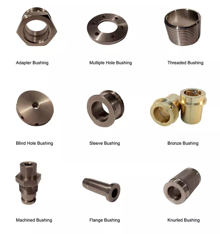
bushing

application

Various industrial applications involve the use of casing. It is an excellent mechanical and chemical material with a wide range of properties. These compounds are also packaged according to national and international standards. Therefore, bushings are used in many different types of machines and equipment. This article will focus on the main industrial applications of casing. This article will also explain what a casing is and what it can do. For more information, click here. Casing application
Among other uses, bushing assemblies are used in aircraft and machinery. For example, a fuel tank of an aircraft may include baffle isolator 40 . The bushing assembly 16 serves as an interface to the fuel tank, allowing electrical current to flow. It can also be used to isolate 1 component from another. In some cases, bushing assemblies are used to provide a tight fit and reduce electrical resistance, which is important in circuits.
The benefits of casing go beyond reducing energy transmission. They reduce lubrication costs. If 2 metal parts are in direct contact, lubrication is required. Thus, the bushing reduces the need for lubrication. They also allow parts of the car to move freely. For example, rubber bushings may begin to deteriorate due to high internal temperatures or cold weather. Also, oil can affect their performance.
For example, bushing CTs in oil and gas circuit breakers are used as window current transformers. It consists of a toroidal core and secondary windings. The center conductor of the bushing acts as the single-turn primary of the BCT. By tapping the secondary winding, the ratio between primary and secondary can be changed. This information can be found on the asset nameplate.
Among other uses, bushings are used in diagnostic equipment. These components require precise positioning. Fortunately, air sleeves are perfect for this purpose. Their frictionless operation eliminates the possibility of misalignment. In addition, products based on porous media help minimize noise. A casing manufacturer can advise you on the best product for your equipment. Therefore, if you are looking for replacement bushings for your existing equipment, please feel free to contact Daikin.

Material

Dry ferrule cores were selected for study and examined under an Olympus polarizing microscope (BX51-P). Core slices showing layers of aluminum foil with a distance of approximately 2 cm between adjacent capacitor screens. The aluminum foil surface has a multi-layered structure with undulations due to shrinkage and crepe. Differences between the 2 types of foils are also revealed.
A typical metal bushing material consists of a high-strength metal backing and a solid lubricant. These materials have higher load-carrying capacity and low friction during operation. Additionally, they are precision machined to tight tolerances. They also offer better thermal conductivity and better fatigue resistance. The accuracy of the metal bushing is improved due to the re-machining process that takes place after the bearing is assembled. Additionally, metal bushing materials are more resistant to wear than plastic bushing materials.
Plastic bushings are relatively inexpensive and readily available off the shelf. Also, the price of custom plastic bushings is relatively low. However, they are not recommended for heavy duty applications. Plastics degrade under high loads and can damage mating parts. Also, if the plastic bushings are not manufactured accurately, they can become misaligned. These are just some of the reasons for choosing metal bushings over plastic.
A mechanically bonded bushing 40 is placed over the stabilizer bar and compressed into the outer sleeve/bracket assembly. The outer metal member includes slotted holes that compensate for the tolerance stacking between the first and second bushing assemblies. Pre-assembly allows the assembly plant to receive a complete assembly ready for vehicle assembly, rather than sub-assembly at the vehicle manufacturing plant.
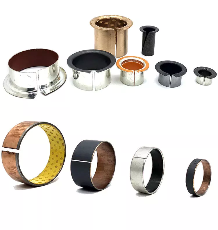
bushing

cost

Control arm bushings are a major component of modern vehicle suspension systems. Damaged bushings can negatively affect the handling and performance of your car. Replacing bushings on a car can cost $200 to $500. While that’s pretty cheap for a handful of control bushings, replacing the entire suspension system could set you back over $1,200. Thankfully, if you want to repair or replace the bushing yourself, you can do it yourself for a fraction of the cost.
If you decide to replace the control arm bushing yourself, it’s best to shop around for the best price. Many auto parts stores offer cheaper bushings that you don’t have to spend a fortune on. Even if you don’t drive for years, rubber can degrade and create cracks in the material. These cracks can be as deep as three-8hs of an inch. This makes it dangerous to drive a car with damaged control arm bushings.
Hiring a mechanic might be a good idea if you don’t like doing the work yourself. You can save money and time by repairing the control arm yourself, but you may have to hire a mechanic to do the job. Replacing the front sway bar bushing alone can cost between $450 and $900. While these components are relatively inexpensive, you can replace them for a better-handling car.
In some cases, sizing the bushings is a more economical option, but if you want to replace your entire suspension system, it’s better to buy a brand new lower limit. You can even save labor by buying a replacement part fork with a good lower portion. In addition to improving your car’s handling and ride, new bushings will add to your car’s overall value. If you are not sure which parts you need, ask your mechanic for a quote.
While the cost of replacing control arm bushings is relatively low, it’s a good idea to compare quotes from multiple mechanics. By getting multiple quotes for the same repair, you can save as much as $50 to $100 on the total cost of your car. In addition to labor costs, parts and labor can vary, so shop around to find the mechanic best suited for your car. There’s no reason to settle for sub-par service when you can save $50 or more!

China supplier The Best Cover Case Bearing Lh Rotavator Spare Parts Used for Dh246f Heavy Plus     with high qualityChina supplier The Best Cover Case Bearing Lh Rotavator Spare Parts Used for Dh246f Heavy Plus     with high quality

China Professional Manufacturer direct sales High Precision Maintenance Type Radial Spherical Plain Bearings GE30   wheel bearing auto parts with Free Design Custom

Product Description

Product Parameters

Spherical Plain Bearings
Bearing Type Granville No. Bore Diameter  Interchangeable Number
Range Bearing No. Bearing No. Bearing No. Bearing No.
Maintenance Type Radial Spherical Plain Bearings GE…E 4-12 GE…E GE…DO GE…E MB…
GE…ES 15-300 GE…ES GE…DO-2RS GE…ES MB…SS
GE…ES-2RS 15-300 GE…ES-2RS   GE…ES-2RS  
GEG…E 4-12 GEH…E GE…FO GE…G MBH…
           
GEG…ES 15-280 GEH…ES GE…FO-2RS GE…GS MBH…SS
GEG…ES-2RS 15-280 GEH…ES-2RS   GE…GS-2RS  
GEEW…ES 12-320 GEG…ES GE…LO   MB…E
GEEW…ES-2RS 20-80 GEM…ES-2RS GE…HO-2RS   MB…ESS
GEZ…ES 12.7-152.4 GEZ…ES GE…ZO SBB… B…L
GEZ…ES-2RS 19.05-152.4 GEZ…ES-2RS GE…ZO-2RS SBB…-2RS B…LSS
GEGZ…ES 31.75-139.7 GEZH…ES     BH…L
GEGZ…ES-2RS 31.75-139.5 GEZH…ES-2RS     BH…LSS
GEWZ…ES 12.7-152.4 GEZM…ES     B…EL
GEWZ…ES-2RS 19.05-152.4 GEZM…ES-2RS     B…ELSS
GEBK…S   GEBJ…S 5-30     PB…  
GEFZ…S   GEC…XS 4.83-25.4   GE…DO   COM…
GEC…XS-2RS 320-460   GE…DO-2RS    
GEF…ES 12-150     SB…A  
GE…XS/K 12-150     SB…  
GEK…XS-2RS 25-60     SA3…A  
Maintenance-free Type Radial Spherical Plain Bearings GE…C 4-30 GE…C GE…UK GE…EC  
GEG…C 4-30 GEH…C GE…FW    
GEFZ…C 4.83-25.4       COM…T
GEBJ…C 5-30        
GE…ET-2RS 15-120 GE…TE-2RS GE…UK-2RS   MB…FSS
GE…ET-2RS/X 15-60 GE…TGR      
GE…XT-2RS 140-300 GE…TA-2RS GE…UK-2RS   MB…LFSS
GE…XT-2RS/X 70-200 GE…TG3A-2RS      
GEG…ET-2RS 15-110   GE…FW-2RS    
GEG…XT-2RS 110-280        
GEZ…ET-2RS 19.05-152.4       B…LFSS
GEC…HT 320-600   GE…DW    
GEH…HC 100-630 GEP…FS      
GEC…XT-2RS 320-460        
GEH…XT-2RS 100-420        
GEJ…HT 100-630        
GE…XF/Q 100-300 GEC…PSA      
GEC…XF/Q 320-460 GEC…PSA      
GEH…XF/Q 100-420 GEC…PSA      
GEH…HF/Q 440-630 GEC…PSA GE…DW    
Angular Contact Spherical Plain Bearings GAC…S 25-200   GE…SX   MB…SA
GACZ…S 12.7-152.4 GAZ…SA     B…SA
GAC…T 25-200   GE…SW    
Spherical Plain Thrust Bearings GX…S 10-200   GE…AX    
GX…T 10-200   GE…AW    


Advantage Products


Company Profile

About Us

Focus on a variety of industries
Provide maintenance solutions
Optimize customer inventory and reduce cost

Established in 2012, HangZhou Granville is a branch of the Granville Group. With our experience, competitive prices and excellent service, we have won the praise of our customers. Our business involves standard and special industrial parts, automotive parts and construction machinery parts required for a variety of different industrial applications.
Our main products include
Bearing series :
ball bearings, deep groove ball bearings, self-aligning ball bearings, angularcontact ball bearings, cylindrical roller bearing, tapered roller bearings, thrust ball bearings, thrust rollerbearings, needle bearings, spherical bearings, joint bearings, pillow blocks, linear bearings, etc.
Accessories series:Automotive Spare Parts,Seals & O-rings ,Power transmission parts Chain and Sprocket
Our products are mainly exported to Europe, America, Middle East, Southeast Asia, India, Pakistan, Bangladesh, Singapore, Korea and other countries around the world. We have a large number of products in stock, which can be delivered with high efficiency in the shortest possible time to solve your matching problems in time. In addition, we have reliable quality and quantity of products to offer. We adhere to the principle of win-win situation and insist on “providing comprehensive quality products and best reputation” to provide excellent services to our customers.

What We Do

Comprehensive product range:
– Bearings
– Oil seals, Transmission belt
– Chain and Sprocket
– Hub assembly & Wheel bearings
– Coupling, castings
– Linear motion

Packaging & Shipping


Our Advantages

1. We have the most advanced bearing process equipment, CNC automatic facilities, and testing instruments.
2. We manufacture ball bearings and mounted bearing units, and also provide a strong full range of products, including electric motors and components One-stop partnerships products from our audited supply chain.
3. All products are manufactured exclusively by companies with ISO 9001:2008 certified Quality Systems which use state-of-the-art machines. The quality path starts from the beginning to deliver and goods’ quality trackable


Our Values
Behavior-based, service-oriented, focused on results and committed to continuous improvement

Factory
To be a leader in providing the best valuable (Reasonable cost, Reliable quality) supply of precision rollers.
Providing this value, will help our customers remain competitive in the global marketplace.


Advantage Manufacturing Processes and Quality Control:

01Heat Treatment
02 Centerless Grinding Machine 11200 (most advanced)
03 Automatic Production Lines for Raceway
04 Automatic Production Lines for Raceway
05 Ultrasonic Cleaning of Rings
06 Automatic Assembly
07 Ultrasonic Cleaning of Bearings
08 Automatic Greasing, Seals Pressing
09Measurement of Bearing Vibration (Acceleration)
10 Measurement of Bearing Vibration (Speed)
11 Laser Marking
12 Automatic Packing

Quality Warranty

Granville as a manufacturer of high quality products, guarantees compliance with the highest standards relative to the use of the best steel quality in the production process, the highest standards in the design of contact surfaces, as well as the most efficient packing and lubrication of parts. From material coming, quality control through all processes. Except interal test, goods to third party inspection if required. After the center of inspection and experiment being founded, effective methods of inspecting all kinds of raw materials are mastered and then the reliability of bearings is ensured. One of our main objectives is the continued improvement in the quality of our products and processes, in pursuit of which we obtained ISO certification 9001:2008 and TS16949. 
 

After Sales Service

  1. Optimize customer inventory and reduce cost
  2. Provide maintenance solutions

FAQ

Q1.Can you accept OEM and customization?
A: Yes. We can customize it according to the samples and drawings you provide.

Q2.Do you keep a stock of these things?
A: In stocks

Q3.Can you provide samples free of charge?
A: Yes. We can provide samples free of charge. But the freight is paid by the customer.

Q4.What’s the delivery date?
A:The delivery time of sample orders is 3 working days.The bulk orders are 5-10 working days.

Q5: Why your price is higher than others?
A: Price = quality . We firmly believe that by the quality of the customer is always get more reliable than on price . So we insist on doing high-quality products.

Q6:What kind of transport do you have ?
A: According to the weight,we will choose the most appropriate mode of transport for you. Our freight forwarding is efficient and cheap.


Types of Miter Gears

The different types of miter gears include Hypoid, Crown, and Spiral. To learn more, read on. In addition, you’ll learn about their differences and similarities. This article will provide an overview of the different types of miter gears. You can also choose the type that fits your needs by using the guide below. After you’ve read it, you’ll know how to use them in your project. You’ll also learn how to pair them up by hand, which is particularly useful if you’re working on a mechanical component.
gear

Bevel gears

Bevel and miter gears are both used to connect 2 shafts that have different axes. In most cases, these gears are used at right angles. The pitch cone of a bevel gear has the same shape as that of a spur gear, except the tooth profile is slightly tapered and has variable depth. The pinions of a bevel gear are normally straight, but can be curved or skew-shaped. They can also have an offset crown wheel with straight teeth relative to the axis.
In addition to their industrial applications, miter gears are found in agriculture, bottling, printing, and various industrial sectors. They are used in coal mining, oil exploration, and chemical processes. They are an important part of conveyors, elevators, kilns, and more. In fact, miter gears are often used in machine tools, like forklifts and jigsaws.
When considering which gear is right for a certain application, you’ll need to think about the application and the design goals. For example, you’ll want to know the maximum load that the gear can carry. You can use computer simulation programs to determine the exact torque required for a specific application. Miter gears are bevel gears that are geared on a single axis, not two.
To calculate the torque required for a particular application, you’ll need to know the MA of each bevel gear. Fortunately, you can now do so with CZPT. With the help of this software, you can generate 3D models of spiral bevel gears. Once you’ve created your model, you can then machine it. This can make your job much easier! And it’s fun!
In terms of manufacturing, straight bevel gears are the easiest to produce. The earliest method for this type of gear is a planer with an indexing head. Since the development of CNC machining, however, more effective manufacturing methods have been developed. These include CZPT, Revacycle, and Coniflex systems. The CZPT uses the Revacycle system. You can also use a CNC mill to manufacture spiral bevel gears.
gear

Hypoid bevel gears

When it comes to designing hypoid bevel gears for miter and other kinds of gears, there are several important parameters to consider. In order to produce high-quality gearings, the mounting distance between the gear teeth and the pinion must be within a predefined tolerance range. In other words, the mounting distance between the gear teeth and pinion must be 0.05 mm or less.
To make this possible, the hypoid bevel gearset mesh is designed to involve sliding action. The result is a quiet transmission. It also means that higher speeds are possible without increasing noise levels. In comparison, bevel gears tend to be noisy at high speeds. For these reasons, the hypoid gearset is the most efficient way to build miter gears. However, it’s important to keep in mind that hypoid gears are not for every application.
Hypoid bevel gears are analogous to spiral bevels, but they don’t have intersecting axes. Because of this, they can produce larger pinions with smooth engagement. Crown bevel gears, on the other hand, have a 90-degree pitch and parallel teeth. Their geometry and pitch is unique, and they have particular geometrical properties. There are different ways to express pitch. The diametral pitch is the number of teeth, while circumferential measurement is called the circumference.
The face-milling method is another technique used for the manufacture of hypoid and spiral bevel gears. Face-milling allows gears to be ground for high accuracy and surface finish. It also allows for the elimination of heat treatment and facilitates the creation of predesigned ease-off topographies. Face-milling increases mechanical resistance by as much as 20%. It also reduces noise levels.
The ANSI/AGMA/ISO standards for geometric dimensioning differ from the best practices for manufacturing hypoid and bevel gears. The violation of common datum surfaces leads to a number of geometrical dimensioning issues. Moreover, hypoid gears need to be designed to incorporate the base pitches of the mating pinion and the hypoid bevel gear. This is not possible without knowing the base pitch of the gear and the mating pinion.

Crown bevel gears

When choosing crown bevels for a miter gear, you will need to consider a number of factors. Specifically, you will need to know the ratio of the tooth load to the bevel gear pitch radius. This will help you choose a bevel gear that possesses the right amount of excitation and load capacity. Crown bevels are also known as helical gears, which are a combination of 2 bevel gear types.
These bevel gears differ from spiral bevels because the bevels are not intersected. This gives you the flexibility of using a larger pinion and smoother engagement. Crown bevel gears are also named for their different tooth portions: the toe, or the part of the gear closest to the bore, and the heel, or the outermost diameter. The tooth height is smaller at the toe than it is at the heel, but the height of the gear is the same at both places.
Crown bevel gears are cylindrical, with teeth that are angled at an angle. They have a 1:1 gear ratio and are used for miter gears and spur gears. Crown bevel gears have a tooth profile that is the same as spur gears but is slightly narrower at the tip, giving them superior quietness. Crown bevel gears for miter gears can be made with an offset pinion.
There are many other options available when choosing a Crown bevel gear for miter gears. The material used for the gears can vary from plastics to pre-hardened alloys. If you are concerned with the material’s strength, you can choose a pre-hardened alloy with a 32-35 Rc hardness. This alloy also has the advantage of being more durable than plastic. In addition to being stronger, crown bevel gears are also easier to lubricate.
Crown bevel gears for miter gears are similar to spiral bevels. However, they have a hyperbolic, not conical, pitch surface. The pinion is often offset above or below the center of the gear, which allows for a larger diameter. Crown bevel gears for miter gears are typically larger than hypoid gears. The hypoid gear is commonly used in automobile rear axles. They are useful when the angle of rotation is 90 degrees. And they can be used for 1:1 ratios.
gear

Spiral miter gears

Spiral bevel gears are produced by machining the face surface of the teeth. The process follows the Hertz theory of elastic contact, where the dislocations are equivalent to small significant dimensions of the contact area and the relative radii of curvature. This method assumes that the surfaces are parallel and that the strains are small. Moreover, it can reduce noise. This makes spiral bevel gears an ideal choice for high-speed applications.
The precision machining of CZPT spiral miter gears reduces backlash. They feature adjustable locking nuts that can precisely adjust the spacing between the gear teeth. The result is reduced backlash and maximum drive life. In addition, these gears are flexible enough to accommodate design changes late in the production process, reducing risk for OEMs and increasing efficiency and productivity. The advantages of spiral miter gears are outlined below.
Spiral bevel gears also have many advantages. The most obvious of these advantages is that they have large-diameter shafts. The larger shaft size allows for a larger diameter gear, but this means a larger gear housing. In turn, this reduces ground clearance, interior space, and weight. It also makes the drive axle gear larger, which reduces ground clearance and interior space. Spiral bevel gears are more efficient than spiral bevel gears, but it may be harder to find the right size for your application.
Another benefit of spiral miter gears is their small size. For the same amount of power, a spiral miter gear is smaller than a straight cut miter gear. Moreover, spiral bevel gears are less likely to bend or pit. They also have higher precision properties. They are suitable for secondary operations. Spiral miter gears are more durable than straight cut ones and can operate at higher speeds.
A key feature of spiral miter gears is their ability to resist wear and tear. Because they are constantly being deformed, they tend to crack in a way that increases their wear and tear. The result is a harder gear with a more contoured grain flow. But it is possible to restore the quality of your gear through proper maintenance. If you have a machine, it would be in your best interest to replace worn parts if they aren’t functioning as they should.

China Professional Manufacturer direct sales High Precision Maintenance Type Radial Spherical Plain Bearings GE30   wheel bearing auto parts     with Free Design CustomChina Professional Manufacturer direct sales High Precision Maintenance Type Radial Spherical Plain Bearings GE30   wheel bearing auto parts     with Free Design Custom

China manufacturer Cixi Bearing High Speed Motorcycle Automotive Truck Bearing Series 6000 6200 6300 Cixi Bearing OEM Auto Parts with Hot selling

Product Description

Specification

The type of  deep groove ball Bearing 6015 used in automobile, tractor, machinery, motor, water pump, agricultural machinery and textile machinery. Its wide application, simple design, non – separation, suitable for high – speed, reliable operation, low maintenance costs.The tight consistency between deep raceway and groove and ball enables deep raceway ball bearings to withstand axial loads in both directions in addition to radial loads.

Product Parameters

Application
1. Automatic controlling machine
2. Semi-conductor industry
3. General industry machinery
4. Medical equipment
5. Solar energy equipment
6. Machine tool
7. Parking system
8. High-speed rail and aviation transportation equipment, etc.

Packaging & Shipping 

Packaging Detail 1.Industrial Exporting Package
2. Individual plastic/Carton/pallet
3. As the customers’ requirements
Delivery Detail 30-45 days for normal order


About us

HangZhou Kent bearing company was established in 2003 and is 1 of the leading bearing manufacturers and exporters in China. Kent specializes in the design and production of high precision, high speed and low noise  groove ball bearings and pillow block bearings. At present, the Corporation has more than 1,000 employees, a fixed assets of 2 billion yuan, and produces 250 million sets of bearings annually. The Corporation’s products are widely used in more than 50 countries and regions under 2 independent brands, namely “BUGAO” and “NBKT”.In addition, we participate in major professional exhibitions at home and abroad every year.

Research and Development

Since 2003, the Corporation has set up a Research & Development Center equipped with multiple laboratories used for precision measurement, mechanical testing, lifespan testing, and physicochemical testing, to continuously upgrade its skills and raise its manufacturing standard and product’s precision. Our workshops are installed with a series of advanced numerically-controlled, grinding and assembly equipment that utilize centralized filtration and cooling systems. Together with the production equipment suppliers, we developed these grinding, ultra-precision, fully automated integrated production lines, and own the intellectual property rights. The precision level of the products are at P5 level and above, with noise level CZPT Z4, V4 and above. Some of our projects have exceeded the 30% precision reserves. Our products are widely used in electric motors, automobiles, motorcycles, household appliances, textile, electric tools and water pump equipment industries, both locally and globally.

Why choose us?
▄ HangZhou Kent bearing Co.,Ltd established in 2003, has been focused on high precision and low noise deep groove ball bearing research and manufacturing. Engaged in foreign trade for 16 years, we provide products for many industrial fields. We attach important to global production, Not only won wideapresd praise in the domestic market, but also gain the recognition of foreign market, such as European,Southeast Asian and Africa market.
▄ The company has more than 20 assembly lines, and through ISO9001:2000 quality management system certification, has a professional technical and service team, technical personnel proportion of more than 30%. Over the years, we have been adhering to the use of high-end raw material production, from the first to every step, with excellent product development capabilities and strict quality control, we continue to expand the product line and application range.
▄ To learn from the advanced level at home and abroad, to create their own high-quality bearings, is the CZPT pursuit of Kent bearing company. Uphold the “True quality is more durable, let the bearing move more quieter”
business philosophy, we have received many customers good praise.
▄ Good Warranty we take customer satisfaction and product quality as the first priority for us, we supply reliable warranties and good after-sales services.

FAQ
1.Q: Are you a factory or trading company?
    A: We are factory specialized in manufacturing and exporting bearings.
2.Q: Where is your factory located? How can I visit there?
    
A: Our factory located in HangZhou county, HangZhou city . You can fly to HangZhou Lishe International Airport directly. All our customers, from home or abroad,are warmly welcome to visit our factory.   
3.Q: Do you provide samples ? it is free charge?
    
A: Yes, we could offer the sample for free charge but do not pay the cost of freight.
4.Q: What is your main product?
    
A: We are making 10 series and total about 100 types of bearings.
5.Q: What is the MOQ for bearings?
    A: Our MOQ is 1000 pieces.

Contact us

Address: Mayan Industry Zone, Henghe Town, HangZhou, HangZhou, China

Worm Shafts and Gearboxes

If you have a gearbox, you may be wondering what the best Worm Shaft is for your application. There are several things to consider, including the Concave shape, Number of threads, and Lubrication. This article will explain each factor and help you choose the right Worm Shaft for your gearbox. There are many options available on the market, so don’t hesitate to shop around. If you are new to the world of gearboxes, read on to learn more about this popular type of gearbox.
worm shaft

Concave shape

The geometry of a worm gear varies considerably depending on its manufacturer and its intended use. Early worms had a basic profile that resembled a screw thread and could be chased on a lathe. Later, tools with a straight sided g-angle were developed to produce threads that were parallel to the worm’s axis. Grinding was also developed to improve the finish of worm threads and minimize distortions that occur with hardening.
To select a worm with the proper geometry, the diameter of the worm gear must be in the same unit as the worm’s shaft. Once the basic profile of the worm gear is determined, the worm gear teeth can be specified. The calculation also involves an angle for the worm shaft to prevent it from overheating. The angle of the worm shaft should be as close to the vertical axis as possible.
Double-enveloping worm gears, on the other hand, do not have a throat around the worm. They are helical gears with a straight worm shaft. Since the teeth of the worm are in contact with each other, they produce significant friction. Unlike double-enveloping worm gears, non-throated worm gears are more compact and can handle smaller loads. They are also easy to manufacture.
The worm gears of different manufacturers offer many advantages. For instance, worm gears are 1 of the most efficient ways to increase torque, while lower-quality materials like bronze are difficult to lubricate. Worm gears also have a low failure rate because they allow for considerable leeway in the design process. Despite the differences between the 2 standards, the overall performance of a worm gear system is the same.
The cone-shaped worm is another type. This is a technological scheme that combines a straight worm shaft with a concave arc. The concave arc is also a useful utility model. Worms with this shape have more than 3 contacts at the same time, which means they can reduce a large diameter without excessive wear. It is also a relatively low-cost model.
worm shaft

Thread pattern

A good worm gear requires a perfect thread pattern. There are a few key parameters that determine how good a thread pattern is. Firstly, the threading pattern must be ACME-threaded. If this is not possible, the thread must be made with straight sides. Then, the linear pitch of the “worm” must be the same as the circular pitch of the corresponding worm wheel. In simple terms, this means the pitch of the “worm” is the same as the circular pitch of the worm wheel. A quick-change gearbox is usually used with this type of worm gear. Alternatively, lead-screw change gears are used instead of a quick-change gear box. The pitch of a worm gear equals the helix angle of a screw.
A worm gear’s axial pitch must match the circular pitch of a gear with a higher axial pitch. The circular pitch is the distance between the points of teeth on the worm, while the axial pitch is the distance between the worm’s teeth. Another factor is the worm’s lead angle. The angle between the pitch cylinder and worm shaft is called its lead angle, and the higher the lead angle, the greater the efficiency of a gear.
Worm gear tooth geometry varies depending on the manufacturer and intended use. In early worms, threading resembled the thread on a screw, and was easily chased using a lathe. Later, grinding improved worm thread finishes and minimized distortions from hardening. As a result, today, most worm gears have a thread pattern corresponding to their size. When selecting a worm gear, make sure to check for the number of threads before purchasing it.
A worm gear’s threading is crucial in its operation. Worm teeth are typically cylindrical, and are arranged in a pattern similar to screw or nut threads. Worm teeth are often formed on an axis of perpendicular compared to their parallel counterparts. Because of this, they have greater torque than their spur gear counterparts. Moreover, the gearing has a low output speed and high torque.

Number of threads

Different types of worm gears use different numbers of threads on their planetary gears. A single threaded worm gear should not be used with a double-threaded worm. A single-threaded worm gear should be used with a single-threaded worm. Single-threaded worms are more effective for speed reduction than double-threaded ones.
The number of threads on a worm’s shaft is a ratio that compares the pitch diameter and number of teeth. In general, worms have 1,2,4 threads, but some have three, five, or six. Counting thread starts can help you determine the number of threads on a worm. A single-threaded worm has fewer threads than a multiple-threaded worm, but a multi-threaded worm will have more threads than a mono-threaded planetary gear.
To measure the number of threads on a worm shaft, a small fixture with 2 ground faces is used. The worm must be removed from its housing so that the finished thread area can be inspected. After identifying the number of threads, simple measurements of the worm’s outside diameter and thread depth are taken. Once the worm has been accounted for, a cast of the tooth space is made using epoxy material. The casting is moulded between the 2 tooth flanks. The V-block fixture rests against the outside diameter of the worm.
The circular pitch of a worm and its axial pitch must match the circular pitch of a larger gear. The axial pitch of a worm is the distance between the points of the teeth on a worm’s pitch diameter. The lead of a thread is the distance a thread travels in 1 revolution. The lead angle is the tangent to the helix of a thread on a cylinder.
The worm gear’s speed transmission ratio is based on the number of threads. A worm gear with a high ratio can be easily reduced in 1 step by using a set of worm gears. However, a multi-thread worm will have more than 2 threads. The worm gear is also more efficient than single-threaded gears. And a worm gear with a high ratio will allow the motor to be used in a variety of applications.
worm shaft

Lubrication

The lubrication of a worm gear is particularly challenging, due to its friction and high sliding contact force. Fortunately, there are several options for lubricants, such as compounded oils. Compounded oils are mineral-based lubricants formulated with 10 percent or more fatty acid, rust and oxidation inhibitors, and other additives. This combination results in improved lubricity, reduced friction, and lower sliding wear.
When choosing a lubricant for a worm shaft, make sure the product’s viscosity is right for the type of gearing used. A low viscosity will make the gearbox difficult to actuate and rotate. Worm gears also undergo a greater sliding motion than rolling motion, so grease must be able to migrate evenly throughout the gearbox. Repeated sliding motions will push the grease away from the contact zone.
Another consideration is the backlash of the gears. Worm gears have high gear ratios, sometimes 300:1. This is important for power applications, but is at the same time inefficient. Worm gears can generate heat during the sliding motion, so a high-quality lubricant is essential. This type of lubricant will reduce heat and ensure optimal performance. The following tips will help you choose the right lubricant for your worm gear.
In low-speed applications, a grease lubricant may be sufficient. In higher-speed applications, it’s best to apply a synthetic lubricant to prevent premature failure and tooth wear. In both cases, lubricant choice depends on the tangential and rotational speed. It is important to follow manufacturer’s guidelines regarding the choice of lubricant. But remember that lubricant choice is not an easy task.

China manufacturer Cixi Bearing High Speed Motorcycle Automotive Truck Bearing Series 6000 6200 6300 Cixi Bearing OEM Auto Parts     with Hot sellingChina manufacturer Cixi Bearing High Speed Motorcycle Automotive Truck Bearing Series 6000 6200 6300 Cixi Bearing OEM Auto Parts     with Hot selling

China high quality Auto Front Wheel Hub Bearing OEM Part No: 6619804902 49X84X48mm with Good quality

Product Description

Cross reference:
90080-36087 front axle wheel bearing
90080-36136 wheel bearing front 
90080-36137 front wheel bearing
90080-36149 wheel hub bearing
90363-40066 front wheel hub bearing
90363-40069 wheel bearing assembly
90363-T0018 wheel bearings
40BVV07-10GCS japanese wheel bearing
DAC4074W-3CS80 japan bearing front wheel bearing

Specifications: 40BWD12 front wheel bearing

Inside Diameter

40 mm

Outside Diameter

74 mm

Width, Outer Race

42 mm

Location

Front Axle Transmission

Position

Left/Right

ABS Equipped

No

Generation

1

Type

Angular contact ball ,double row


Advance auto parts wheel bearing size list

P.N. d D B Mass (kg)
25BWD01 25 52 42 0.36
27BWD01J 27 60 50 0.36
28BWD03A 28 58 42 0.4
28BWD01A 28 61 42 0.53
30BWD08 30 55 26 0.26
30BWD01A 30 63 42 0.55
30BWD04 30 68 45 0.69
32BWD05 32 72 45 0.8
34BWD04B 34 64 37 0.82
34BWD11 34 64 37 0.46
34BWD10B 34 66 37 0.51
34BWD07B 34 68 42 0.64
34BWD09A 34 68 37 0.54
35BWD19E 35 65 37 0.48
35BWD07 35 68 30 0.48
35BWD07A 35 68 30 0.48
35BWD16 35 68 36 0.48
35BWD06A 35 72 31 0.55
36BWD04 36 68 33 0.48
36BWD03 36 72 42 0.68

Our main products:


Applications of Spline Couplings

A spline coupling is a highly effective means of connecting 2 or more components. These types of couplings are very efficient, as they combine linear motion with rotation, and their efficiency makes them a desirable choice in numerous applications. Read on to learn more about the main characteristics and applications of spline couplings. You will also be able to determine the predicted operation and wear. You can easily design your own couplings by following the steps outlined below.
splineshaft

Optimal design

The spline coupling plays an important role in transmitting torque. It consists of a hub and a shaft with splines that are in surface contact without relative motion. Because they are connected, their angular velocity is the same. The splines can be designed with any profile that minimizes friction. Because they are in contact with each other, the load is not evenly distributed, concentrating on a small area, which can deform the hub surface.
Optimal spline coupling design takes into account several factors, including weight, material characteristics, and performance requirements. In the aeronautics industry, weight is an important design factor. S.A.E. and ANSI tables do not account for weight when calculating the performance requirements of spline couplings. Another critical factor is space. Spline couplings may need to fit in tight spaces, or they may be subject to other configuration constraints.
Optimal design of spline couplers may be characterized by an odd number of teeth. However, this is not always the case. If the external spline’s outer diameter exceeds a certain threshold, the optimal spline coupling model may not be an optimal choice for this application. To optimize a spline coupling for a specific application, the user may need to consider the sizing method that is most appropriate for their application.
Once a design is generated, the next step is to test the resulting spline coupling. The system must check for any design constraints and validate that it can be produced using modern manufacturing techniques. The resulting spline coupling model is then exported to an optimisation tool for further analysis. The method enables a designer to easily manipulate the design of a spline coupling and reduce its weight.
The spline coupling model 20 includes the major structural features of a spline coupling. A product model software program 10 stores default values for each of the spline coupling’s specifications. The resulting spline model is then calculated in accordance with the algorithm used in the present invention. The software allows the designer to enter the spline coupling’s radii, thickness, and orientation.
splineshaft

Characteristics

An important aspect of aero-engine splines is the load distribution among the teeth. The researchers have performed experimental tests and have analyzed the effect of lubrication conditions on the coupling behavior. Then, they devised a theoretical model using a Ruiz parameter to simulate the actual working conditions of spline couplings. This model explains the wear damage caused by the spline couplings by considering the influence of friction, misalignment, and other conditions that are relevant to the splines’ performance.
In order to design a spline coupling, the user first inputs the design criteria for sizing load carrying sections, including the external spline 40 of the spline coupling model 30. Then, the user specifies torque margin performance requirement specifications, such as the yield limit, plastic buckling, and creep buckling. The software program then automatically calculates the size and configuration of the load carrying sections and the shaft. These specifications are then entered into the model software program 10 as specification values.
Various spline coupling configuration specifications are input on the GUI screen 80. The software program 10 then generates a spline coupling model by storing default values for the various specifications. The user then can manipulate the spline coupling model by modifying its various specifications. The final result will be a computer-aided design that enables designers to optimize spline couplings based on their performance and design specifications.
The spline coupling model software program continually evaluates the validity of spline coupling models for a particular application. For example, if a user enters a data value signal corresponding to a parameter signal, the software compares the value of the signal entered to the corresponding value in the knowledge base. If the values are outside the specifications, a warning message is displayed. Once this comparison is completed, the spline coupling model software program outputs a report with the results.
Various spline coupling design factors include weight, material properties, and performance requirements. Weight is 1 of the most important design factors, particularly in the aeronautics field. ANSI and S.A.E. tables do not consider these factors when calculating the load characteristics of spline couplings. Other design requirements may also restrict the configuration of a spline coupling.

Applications

Spline couplings are a type of mechanical joint that connects 2 rotating shafts. Its 2 parts engage teeth that transfer load. Although splines are commonly over-dimensioned, they are still prone to fatigue and static behavior. These properties also make them prone to wear and tear. Therefore, proper design and selection are vital to minimize wear and tear on splines. There are many applications of spline couplings.
A key design is based on the size of the shaft being joined. This allows for the proper spacing of the keys. A novel method of hobbing allows for the formation of tapered bases without interference, and the root of the keys is concentric with the axis. These features enable for high production rates. Various applications of spline couplings can be found in various industries. To learn more, read on.
FE based methodology can predict the wear rate of spline couplings by including the evolution of the coefficient of friction. This method can predict fretting wear from simple round-on-flat geometry, and has been calibrated with experimental data. The predicted wear rate is reasonable compared to the experimental data. Friction evolution in spline couplings depends on the spline geometry. It is also crucial to consider the lubrication condition of the splines.
Using a spline coupling reduces backlash and ensures proper alignment of mated components. The shaft’s splined tooth form transfers rotation from the splined shaft to the internal splined member, which may be a gear or other rotary device. A spline coupling’s root strength and torque requirements determine the type of spline coupling that should be used.
The spline root is usually flat and has a crown on 1 side. The crowned spline has a symmetrical crown at the centerline of the face-width of the spline. As the spline length decreases toward the ends, the teeth are becoming thinner. The tooth diameter is measured in pitch. This means that the male spline has a flat root and a crowned spline.
splineshaft

Predictability

Spindle couplings are used in rotating machinery to connect 2 shafts. They are composed of 2 parts with teeth that engage each other and transfer load. Spline couplings are commonly over-dimensioned and are prone to static and fatigue behavior. Wear phenomena are also a common problem with splines. To address these issues, it is essential to understand the behavior and predictability of these couplings.
Dynamic behavior of spline-rotor couplings is often unclear, particularly if the system is not integrated with the rotor. For example, when a misalignment is not present, the main response frequency is 1 X-rotating speed. As the misalignment increases, the system starts to vibrate in complex ways. Furthermore, as the shaft orbits depart from the origin, the magnitudes of all the frequencies increase. Thus, research results are useful in determining proper design and troubleshooting of rotor systems.
The model of misaligned spline couplings can be obtained by analyzing the stress-compression relationships between 2 spline pairs. The meshing force model of splines is a function of the system mass, transmitting torque, and dynamic vibration displacement. This model holds when the dynamic vibration displacement is small. Besides, the CZPT stepping integration method is stable and has high efficiency.
The slip distributions are a function of the state of lubrication, coefficient of friction, and loading cycles. The predicted wear depths are well within the range of measured values. These predictions are based on the slip distributions. The methodology predicts increased wear under lightly lubricated conditions, but not under added lubrication. The lubrication condition and coefficient of friction are the key factors determining the wear behavior of splines.

China high quality Auto Front Wheel Hub Bearing OEM Part No: 6619804902 49X84X48mm     with Good qualityChina high quality Auto Front Wheel Hub Bearing OEM Part No: 6619804902 49X84X48mm     with Good quality