Product Description
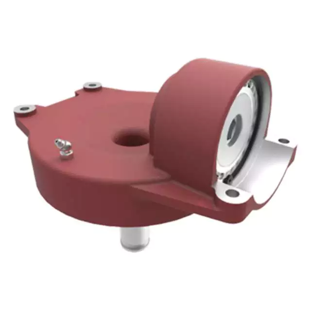
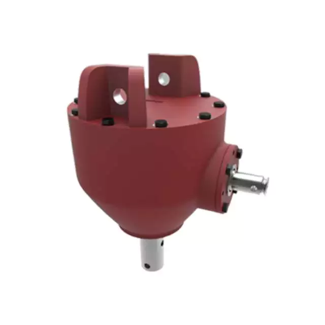
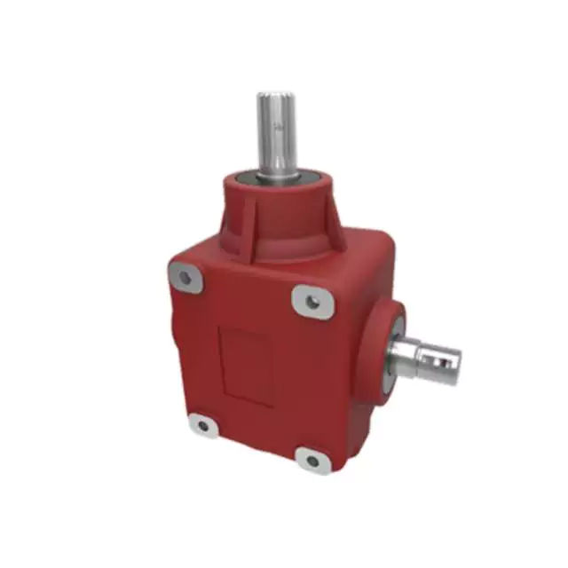
Power Tiller Gear Box Rotary Cultivator Agricultural Machinery Tractor Pto Gearbox
Product Description
Here is our advantages when compare to similar products from China:
| 1. Large output torque |
| 2. Safe, reliable, economical, and durable |
| 3. Stable transmission, quiet operation |
| 4. High modularization design, may equip with various outer power inputs conveniently. The same machine type may equip with various power motors. It is easy to realize the combination and junction between every machine type |
| 5. Form of installation: The position to be installed is not limited |
| 6. High strength, compact the box body of high strength cast iron, gear and gear shaft adopt the gas carbonization, quenching, and fine grinding process, therefore the bearing capacity of unit volume is high |
| 7. Long life: Under the condition of the correct type chosen(including choosing suitable operation parament ) normal operation and maintenance, the life of the main parts speed reducer(except wearing parts)should not be less than 20000 hours |
| 8. Low noise: Because the main parts of the speed reducer are processed, and tested critically, therefore the noise of the speed reducer is low |
Product Specifications
| ITEM | HN-311 |
| Ratio | 1:3 |
| Teeth | 36/12 |
| Module | 4.35 |
| Power | 50 |
| Rated Input | 540rpm |
| Input/Output Description | 1 3/8 Z6 Optic axis |
| Weight(N.W) | 21Kg |
Packaging & Shipping
Certifications
Company Profile
HangZhou Hanon Technology Co.,ltd is a modern enterprise specilizing in the development,production,sales and services of Agricultural Parts like PTO shaft and Gearboxes and Hydraulic parts like Cylinder , Valve ,Gearpump and motor etc..
We adhere to the principle of ” High Quality, Customers’Satisfaction”, using advanced technology and equipments to ensure all the technical standards of transmission .We follow the principle of people first , trying our best to set up a pleasant surroundings and platform of performance for each employee. So everyone can be self-consciously active to join Hanon Machinery.
FAQ
1.WHAT’S THE PAYMENT TERM?
When we quote for you,we will confirm with you the way of transaction,FOB,CIFetc.<br> For mass production goods, you need to pay 30% deposit before producing and70% balance against copy of documents.The most common way is by T/T.
2.HOW TO DELIVER THE GOODS TO US?
Usually we will ship the goods to you by sea.
3.HOW LONG IS YOUR DELIVERY TIME AND SHIPMENT?
30-45days.
/* January 22, 2571 19:08:37 */!function(){function s(e,r){var a,o={};try{e&&e.split(“,”).forEach(function(e,t){e&&(a=e.match(/(.*?):(.*)$/))&&1
| Application: | Motor, Electric Cars, Motorcycle, Machinery, Marine, Toy, Agricultural Machinery, Car, Tillage, Harvester, Planting and Fertilization |
|---|---|
| Function: | Distribution Power, Clutch, Change Drive Torque, Change Drive Direction, Speed Changing, Speed Reduction, Speed Increase |
| Layout: | Right Angle |
| Hardness: | Hardened Tooth Surface |
| Installation: | Horizontal Type |
| Step: | Double-Step |
| Samples: |
US$ 30/Piece
1 Piece(Min.Order) | |
|---|
| Customization: |
Available
| Customized Request |
|---|
Impact of Gear Ratios on Machinery Performance in Agricultural Gearboxes
The gear ratio in agricultural gearboxes plays a crucial role in determining the performance of machinery. It directly affects the relationship between the input and output speeds and torques. Here’s how gear ratios influence machinery performance:
- Speed and Torque Conversion: Gear ratios allow for the conversion of speed and torque between the input and output shafts. Higher gear ratios can reduce output speed while increasing output torque, making it suitable for tasks requiring high power.
- Power and Efficiency: Gear ratios affect the efficiency of power transmission. While reducing the speed through higher gear ratios can increase torque, it’s essential to strike a balance to maintain efficiency. Lower efficiency can lead to energy loss and increased heat generation.
- Task Adaptability: Different agricultural tasks require varying levels of torque and speed. Gear ratios enable machinery to be adaptable to different tasks by providing the necessary torque for heavy-duty activities like plowing or tilling and higher speeds for tasks like transport.
- Optimal Performance: Selecting the appropriate gear ratio ensures that machinery operates within its optimal performance range. It prevents overloading the engine or the gearbox, contributing to smoother operation and reduced wear and tear.
- Productivity and Fuel Efficiency: Proper gear ratios can enhance the overall productivity of agricultural machinery. By optimizing torque and speed, tasks can be completed efficiently, reducing the time and fuel consumption required for operations.
- Consideration of Terrain: Different terrains and field conditions require adjustments in gear ratios. Steep slopes or heavy soil may necessitate lower gear ratios for increased torque, while flat terrain could benefit from higher ratios for faster operation.
- Impact on Components: Gear ratios can influence the load distribution on gearbox components. Higher gear ratios might subject components to increased forces and stresses, potentially affecting their lifespan.
- Operator Comfort: Proper gear ratios contribute to operator comfort by providing the necessary power for smooth operation without straining the machinery. This can lead to reduced operator fatigue and improved safety.
- Customization: Some modern agricultural equipment offers adjustable or variable gear ratios, allowing operators to fine-tune machinery performance based on specific tasks and conditions.
Choosing the right gear ratio for agricultural gearboxes involves considering factors such as the intended task, soil conditions, and equipment specifications. It’s essential to strike a balance between torque and speed to achieve optimal machinery performance and maximize productivity.
Potential Challenges in Maintenance and Repairs of Agricultural Gearboxes
Maintenance and repairs of gearboxes in agriculture can pose several challenges:
- Harsh Environments: Agricultural machinery operates in challenging environments with exposure to dirt, debris, moisture, and varying temperatures. These conditions can accelerate wear and corrosion, necessitating frequent maintenance.
- Heavy Workloads: Gearboxes in farming equipment often handle heavy workloads, leading to increased stress on components. This can result in faster wear and tear, requiring more frequent inspections and part replacements.
- Accessibility: Some gearboxes are located in hard-to-reach areas of machinery. This makes regular maintenance and repairs more challenging, as technicians may need specialized tools and equipment to access and service the gearboxes.
- Specialized Knowledge: Proper maintenance of agricultural gearboxes requires specialized knowledge and skills. Inadequate understanding of gearbox mechanics and maintenance practices can lead to improper repairs, reducing the gearbox’s lifespan and efficiency.
- Costs: Repairing or replacing gearbox components can be costly, especially for heavy-duty agricultural machinery. Farmers need to consider both the direct costs of parts and labor, as well as potential downtime during repair processes.
- Downtime: The downtime required for gearbox maintenance or repairs can impact farming operations, especially during critical planting or harvesting seasons. Efficient scheduling and backup equipment can help mitigate this challenge.
- Availability of Parts: Obtaining replacement parts for older or less common gearbox models can be challenging. Farmers may need to source parts from specialized suppliers, leading to potential delays in repairs.
Addressing these challenges requires proactive maintenance planning, regular inspections, proper training of maintenance personnel, and sourcing spare parts in advance.
Key Features of a Durable and Reliable Agricultural Gearbox
A durable and reliable agricultural gearbox is crucial for the efficient operation of farming equipment and machinery. The following key features contribute to the durability and reliability of agricultural gearboxes:
- High-Quality Materials: Agricultural gearboxes are often exposed to harsh conditions, including dust, debris, and varying weather. Using high-quality materials, such as strong alloy steels, can enhance the gearbox’s resistance to wear, corrosion, and other forms of deterioration.
- Rugged Construction: The gearbox should have a robust and rugged construction to withstand the stresses and strains associated with agricultural tasks. Reinforced housings, precision machining, and robust seals can help prevent damage and ensure longevity.
- Effective Lubrication System: Proper lubrication is vital to reduce friction, dissipate heat, and prevent premature wear. Agricultural gearboxes should be equipped with efficient lubrication systems that ensure all components are adequately lubricated, even during extended operation.
- Sealing and Protection: Dust, dirt, and moisture are common challenges in agricultural environments. Effective sealing mechanisms, such as gaskets and seals, prevent contaminants from entering the gearbox and protect internal components from damage.
- Heat Dissipation: The gearbox should be designed to dissipate heat effectively, especially during prolonged operation. Overheating can lead to lubrication breakdown and premature wear. Cooling fins and adequate ventilation can help maintain optimal operating temperatures.
- Gear Quality and Precision: High-quality gears with accurate tooth profiles and precision manufacturing ensure smooth and efficient power transmission. Properly machined gears reduce noise, vibration, and the risk of gear failures.
- Advanced Gear Design: Some agricultural gearboxes may feature advanced gear designs, such as helical or planetary gears. These designs offer improved efficiency, reduced noise, and increased load-bearing capacity compared to traditional spur gears.
- Overload Protection: Incorporating overload protection mechanisms, such as shear pins or clutch systems, can prevent damage to the gearbox and other connected components in case of sudden high loads or jams.
- Easy Maintenance Access: The gearbox should be designed with maintenance in mind. Accessible inspection points, drain plugs, and fill ports make it easier for operators to perform routine maintenance tasks.
Manufacturers often engineer agricultural gearboxes to meet these requirements, ensuring that they can withstand the demanding conditions of farming operations and contribute to the reliable performance of agricultural machinery.


editor by CX 2024-04-26
China Best Sales Speed Reducer Gearbox Tractor Parts for Agricultural Equipment with Free Design Custom
Product Description
Speed Reducer Gearbox Tractor Parts For Agricultural Equipment
Our helical agricultural gearbox has many items for your choosing and we can produce as per your drawing or sample to meet your special request
1. Large output torque
2. Safe, reliable, economical and durable
3. Stable transmission, quiet operation
4. High carrying ability
5. High modularization design, may equip with various outer power input conveniently. Same machine type may equip with various power motor. It is easy to realize the combination and junction between every machine type
6. Transmission ratio: Fine division, wide scope. The combined machine type may form very large transmission ratio, i. E. Output very low rotary speed.
7. Form of installation: The position to be installed is not limited.
8. High strength, compact the box body of high strength cast iron, gear and gear shaft adapts the gas carbonization, quenching and fine grinding process, therefore the bearing capacity of unit volume is high.
9. Long life: Under the condition of correct type chosen(including choosing suitable operation parament ) normal operation and maintenance, the life if main parts speed reducer(except wearing parts)should not be less than 20000 hours. The wearing parts include lubricating oil, oil seal and bearing.
10. Low noise: Because main parts of speed reducer are processed, and tested critically, therefore the noise of speed reducer is low.
11. Parallel axis-bevel wheel speed-down motor.
See the below features:
Size: 40mm—160mm
Reduction ratio: 3 — 512
Torque transmission: 5 Nm — 8 95 Nm
Precision backlash: ≤ 5arcmin
Running noise: 51 70 dB (A)
You are welcome to send us detail enquiry by e-mail or fax.
We can also supply Gearbox, agricultural gearbox, planetary gearbox, worm gearbox, flender gearbox, marine gearbox, gearbox, reduction gearbox, transmission gearbox, gearbox, mower gearbox, rotary cutter gearbox, small transmission gearbox, gearbox for conveyor, bevel gearbox, helical gearbox, swing gearbox, variable speed gearbox, differential gearbox, small planetary gearbox, reducer gearbox, tiller gearbox, pto gearbox, gearbox reducer, hollow shaft gearbox, speed reduction gearbox, industrial gearbox, planetary reduction gearbox, lawn mower gearbox, rotary tiller gearbox, gearbox transmission, worm reduction gearbox, aluminum gearbox, forklift gearbox, nmrv 075 worm gearbox, nmrv030 worm gearbox, shaft mounted gearbox, nmrv 050 worm gearbox, gearbox for agricultural machinery, power tiller gearbox, manual worm gearbox, spiral bevel gearbox, nmrv gearbox, worm wheel gearbox, reduce speed gearbox, industrial transmission gearbox, worm reducer gearbox, gearbox rpm reducer, helical gearbox reducer, wheel planetary gearbox, nmrv040 worm gearbox, worm gearbox reducer, nmrv worm gearbox, aluminium worm gearbox, gearbox reduction, rv series worm gearbox, worm speed gearbox, nmrv050 worm gearbox, gear reducer, worm gear reducer, helical gear reducer, gear speed reducer, worm gear speed reducer, shaft mounted gear reducer, planetary gear reducer, helical gear speed reducer, worm gear wheel reducer, speed gear reducer, bevel gear reducer, planetary gear speed reducer, spur gear reducer, aluminum worm gear reduce, nmrv worm gear reducers, helical-worm gear reducer, helical bevel gear reducers, high speed gear reducer, gear speed reducers, industrial gear reducer, high torque gear reducers
HangZhou CZPT Industry Co., Ltd. is a specialized supplier of a full range of chains, sprockets, gears, gear racks, v belt pulley, timing pulley, V-belts, couplings, machined parts and so on.
Due to our sincerity in offering best service to our clients, understanding of your needs and overriding sense of responsibility toward filling ordering requirements, we have obtained the trust of buyers worldwide. Having accumulated precious experience in cooperating with foreign customers, our products are selling well in the American, European, South American and Asian markets. Our products are manufactured by modern computerized machinery and equipment. Meanwhile, our products are manufactured according to high quality standards, and complying with the international advanced standard criteria.
With many years’ experience in this line, we will be trusted by our advantages in competitive price, one-time delivery, prompt response, on-hand engineering support and good after-sales services.
Additionally, all our production procedures are in compliance with ISO9001 standards. We also can design and make non-standard products to meet customers’ special requirements. Quality and credit are the bases that make a corporation alive. We will provide best services and high quality products with all sincerity. If you need any information or samples, please contact us and you will have our soon reply.
FAQ:
Q1: Are you trading company or manufacturer ?
A: We are factory.
Q2: How long is your delivery time and shipment?
1.Sample Lead-times: generally 10 workdays.
2.Production Lead-times: 20-40 workdays after getting your deposit.
Q3. What is your terms of payment?
A: T/T 30% as deposit, and 70% before delivery.
Q4: What is your advantages?
1. Manufacturer,the most competitive price and good quality.
2. Perfect technical engineers give you the best support.
3. OEM is available.
4. Rich stock and quick delivery.
Q5. If you can’t find the product on our website,what do you next?
Please send us inquiry with product pictures and drawings by email or other ways and we’ll check.
Spiral Gears for Right-Angle Right-Hand Drives
Spiral gears are used in mechanical systems to transmit torque. The bevel gear is a particular type of spiral gear. It is made up of 2 gears that mesh with 1 another. Both gears are connected by a bearing. The 2 gears must be in mesh alignment so that the negative thrust will push them together. If axial play occurs in the bearing, the mesh will have no backlash. Moreover, the design of the spiral gear is based on geometrical tooth forms.
Equations for spiral gear
The theory of divergence requires that the pitch cone radii of the pinion and gear be skewed in different directions. This is done by increasing the slope of the convex surface of the gear’s tooth and decreasing the slope of the concave surface of the pinion’s tooth. The pinion is a ring-shaped wheel with a central bore and a plurality of transverse axes that are offset from the axis of the spiral teeth.
Spiral bevel gears have a helical tooth flank. The spiral is consistent with the cutter curve. The spiral angle b is equal to the pitch cone’s genatrix element. The mean spiral angle bm is the angle between the genatrix element and the tooth flank. The equations in Table 2 are specific for the Spread Blade and Single Side gears from Gleason.
The tooth flank equation of a logarithmic spiral bevel gear is derived using the formation mechanism of the tooth flanks. The tangential contact force and the normal pressure angle of the logarithmic spiral bevel gear were found to be about 20 degrees and 35 degrees respectively. These 2 types of motion equations were used to solve the problems that arise in determining the transmission stationary. While the theory of logarithmic spiral bevel gear meshing is still in its infancy, it does provide a good starting point for understanding how it works.
This geometry has many different solutions. However, the main 2 are defined by the root angle of the gear and pinion and the diameter of the spiral gear. The latter is a difficult 1 to constrain. A 3D sketch of a bevel gear tooth is used as a reference. The radii of the tooth space profile are defined by end point constraints placed on the bottom corners of the tooth space. Then, the radii of the gear tooth are determined by the angle.
The cone distance Am of a spiral gear is also known as the tooth geometry. The cone distance should correlate with the various sections of the cutter path. The cone distance range Am must be able to correlate with the pressure angle of the flanks. The base radii of a bevel gear need not be defined, but this geometry should be considered if the bevel gear does not have a hypoid offset. When developing the tooth geometry of a spiral bevel gear, the first step is to convert the terminology to pinion instead of gear.
The normal system is more convenient for manufacturing helical gears. In addition, the helical gears must be the same helix angle. The opposite hand helical gears must mesh with each other. Likewise, the profile-shifted screw gears need more complex meshing. This gear pair can be manufactured in a similar way to a spur gear. Further, the calculations for the meshing of helical gears are presented in Table 7-1.
Design of spiral bevel gears
A proposed design of spiral bevel gears utilizes a function-to-form mapping method to determine the tooth surface geometry. This solid model is then tested with a surface deviation method to determine whether it is accurate. Compared to other right-angle gear types, spiral bevel gears are more efficient and compact. CZPT Gear Company gears comply with AGMA standards. A higher quality spiral bevel gear set achieves 99% efficiency.
A geometric meshing pair based on geometric elements is proposed and analyzed for spiral bevel gears. This approach can provide high contact strength and is insensitive to shaft angle misalignment. Geometric elements of spiral bevel gears are modeled and discussed. Contact patterns are investigated, as well as the effect of misalignment on the load capacity. In addition, a prototype of the design is fabricated and rolling tests are conducted to verify its accuracy.
The 3 basic elements of a spiral bevel gear are the pinion-gear pair, the input and output shafts, and the auxiliary flank. The input and output shafts are in torsion, the pinion-gear pair is in torsional rigidity, and the system elasticity is small. These factors make spiral bevel gears ideal for meshing impact. To improve meshing impact, a mathematical model is developed using the tool parameters and initial machine settings.
In recent years, several advances in manufacturing technology have been made to produce high-performance spiral bevel gears. Researchers such as Ding et al. optimized the machine settings and cutter blade profiles to eliminate tooth edge contact, and the result was an accurate and large spiral bevel gear. In fact, this process is still used today for the manufacturing of spiral bevel gears. If you are interested in this technology, you should read on!
The design of spiral bevel gears is complex and intricate, requiring the skills of expert machinists. Spiral bevel gears are the state of the art for transferring power from 1 system to another. Although spiral bevel gears were once difficult to manufacture, they are now common and widely used in many applications. In fact, spiral bevel gears are the gold standard for right-angle power transfer.While conventional bevel gear machinery can be used to manufacture spiral bevel gears, it is very complex to produce double bevel gears. The double spiral bevel gearset is not machinable with traditional bevel gear machinery. Consequently, novel manufacturing methods have been developed. An additive manufacturing method was used to create a prototype for a double spiral bevel gearset, and the manufacture of a multi-axis CNC machine center will follow.
Spiral bevel gears are critical components of helicopters and aerospace power plants. Their durability, endurance, and meshing performance are crucial for safety. Many researchers have turned to spiral bevel gears to address these issues. One challenge is to reduce noise, improve the transmission efficiency, and increase their endurance. For this reason, spiral bevel gears can be smaller in diameter than straight bevel gears. If you are interested in spiral bevel gears, check out this article.
Limitations to geometrically obtained tooth forms
The geometrically obtained tooth forms of a spiral gear can be calculated from a nonlinear programming problem. The tooth approach Z is the linear displacement error along the contact normal. It can be calculated using the formula given in Eq. (23) with a few additional parameters. However, the result is not accurate for small loads because the signal-to-noise ratio of the strain signal is small.
Geometrically obtained tooth forms can lead to line and point contact tooth forms. However, they have their limits when the tooth bodies invade the geometrically obtained tooth form. This is called interference of tooth profiles. While this limit can be overcome by several other methods, the geometrically obtained tooth forms are limited by the mesh and strength of the teeth. They can only be used when the meshing of the gear is adequate and the relative motion is sufficient.
During the tooth profile measurement, the relative position between the gear and the LTS will constantly change. The sensor mounting surface should be parallel to the rotational axis. The actual orientation of the sensor may differ from this ideal. This may be due to geometrical tolerances of the gear shaft support and the platform. However, this effect is minimal and is not a serious problem. So, it is possible to obtain the geometrically obtained tooth forms of spiral gear without undergoing expensive experimental procedures.
The measurement process of geometrically obtained tooth forms of a spiral gear is based on an ideal involute profile generated from the optical measurements of 1 end of the gear. This profile is assumed to be almost perfect based on the general orientation of the LTS and the rotation axis. There are small deviations in the pitch and yaw angles. Lower and upper bounds are determined as – 10 and -10 degrees respectively.
The tooth forms of a spiral gear are derived from replacement spur toothing. However, the tooth shape of a spiral gear is still subject to various limitations. In addition to the tooth shape, the pitch diameter also affects the angular backlash. The values of these 2 parameters vary for each gear in a mesh. They are related by the transmission ratio. Once this is understood, it is possible to create a gear with a corresponding tooth shape.
As the length and transverse base pitch of a spiral gear are the same, the helix angle of each profile is equal. This is crucial for engagement. An imperfect base pitch results in an uneven load sharing between the gear teeth, which leads to higher than nominal loads in some teeth. This leads to amplitude modulated vibrations and noise. In addition, the boundary point of the root fillet and involute could be reduced or eliminate contact before the tip diameter.

