Tag Archives: tractor sales

China Agricultural Liquid Regulator JH With Pressure Gauge Pesticide Boom Sprayer Liquid Fertilizer Boom Tractor Spare Parts with Best Sales

Situation: New
Guarantee: 1.5 years
Applicable Industries: Manufacturing Plant, Farms, Food Shop, Printing Stores
Bodyweight (KG): 5 KG
Showroom Location: Canada, Turkey, Italy, France, Philippines, Brazil, Peru, Rear Axle For Bu Yang 300CC D300 BY300 ATV 4.1.01.0041 HangZhou 300CC Rear Shaft India, Kenya, Argentina
Online video outgoing-inspection: Supplied
Machinery Test Report: Supplied
Advertising Type: Common Item
Kind: Bearing
Use: Tractors
Merchandise Identify: Tractor Spare Parts
Software: Plant Protection
Materials: Superior Nylon
Usage: Tractor Put into action Farm Equipment
Dimensions: Regular Size
Model: Assorted Model
MOQ: 1
Certification: CE
Title: Tractor- Spraying Liquid Distributor
OEM: Suitable

Business Information
Packaging & Shipping and delivery
FAQQ: What is your payment terms?
A: Typically we acknowledge T/T ,Western Union or PayPal.

Q: What is your transport item?
A: We ship objects through EMS, DHL, UPS, TNT, Deft Layout NG0144705710-A Trailer Axle Elements & Equipment Return Spring China Submit or Hong Kong Submit.

Q: What is actually your shipping and delivery time?
A. 1. The stock samples can be sent to you in 3-5days by international specific soon after acquired
2. The batch purchase can be delivered to you in about 10-15days soon after purchase affirmation (by air or by sea)

Q: What is your major products of your firm?
A: We specialised in all types of water pump(drinking water pump,micro gear pump,high performance diaphragm pump,Marine pump,RV pump )for more than ten years with exceptional good quality and competitive

Q:How can I decide on the most ideal pump? A: Please tell me your thorough movement fee, voltage, application and so on, then I will match the most proper pump for you, CN91 OEM Outboard Brief Shaft Foredom Flex Shaft Cast Boat And Ship Stern Shaft or you can decide on the actual design in the merchandise manual.

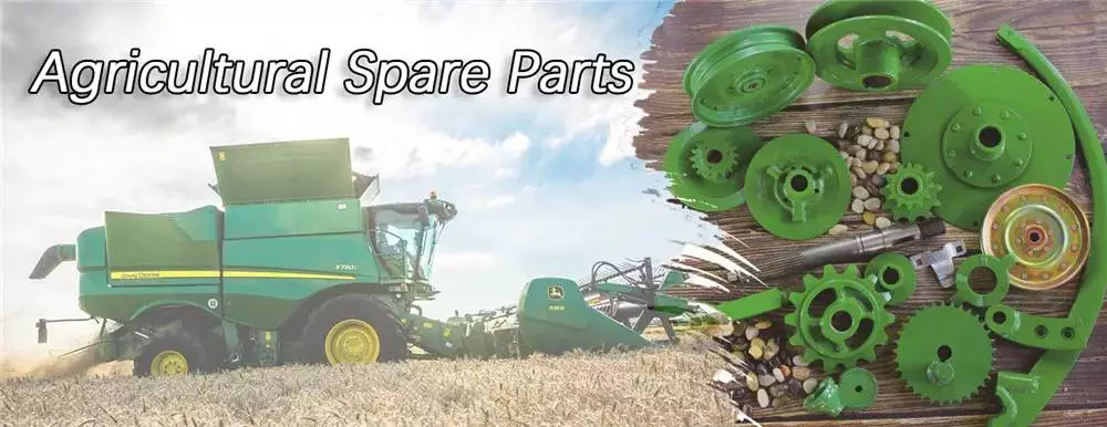
Types of agricultural parts

Agricultural parts can be divided into different categories. These components include tractors, moldboard plows, whips and sickles. Some of the different types of agricultural ingredients are listed below. Each of these parts is important for different types of farming. It is important to know the purpose of each and what it does. If you are a farmer or plan to become a farmer, these parts are critical to your operation.
agriculturalparts

Tractor

The first tractor appeared in the 1920s. Ford and International Harvester were among the first companies to produce farm tractors, but the industry has grown rapidly. By the 1920s, hundreds of companies were producing farm tractors. The agricultural depression of the 1930s forced many of these companies out of business. By the 1930s, only seven companies were major players in the tractor business. Ford produced the largest number of wheeled tractors in the United States between 1930 and 1955.
Some tractors are equipped with various accessories to enhance their performance. These specialized agricultural components are used for a variety of tasks. These include tillage, harvesting, planting and material handling. Tractors vary in horsepower, lift capacity, control and capabilities. Some models also have device mounting options. The downside of this is that if you need to use the tractor for other purposes, you will have to use additional attachments that can damage the tractor.
Modern tractors have a clutch pedal on the gear lever. This allows you to shift quickly without pedaling. Other tractors have a throttle speed button that improves hydraulic flow to the implement. However, the most important component of a tractor is the engine. Tractors must be driven safely because even minor accidents can cause serious damage to farm equipment. While there are many tractors that can operate without these parts, you can find the right tractor for your job.

Shared plows

One of the many uses of shared plows as part of agriculture is to increase the amount of soil in a field. This plow effectively removes compacted soil and lifts weed roots. According to the University of Nebraska-Lincoln Institute for Agriculture and Natural Resources, plowshares are best used in the fall, when weeds are less active and the soil is more fertile.
The basic plowshare can be adjusted by raising or lowering the plowshare to suit runners in the furrow. However, this design is not suitable for breaking up the heavier soils of northern Europe. In the 6th century, however, the advent of the wheel made it possible to use larger moldboards, which increased food production and population growth. Today, farmers in North America have access to a wide variety of moldboard plows.
Agricultural moldboard plows come in two basic styles, horse-drawn or tractor-style. Horse-drawn models have one bottom, while tractor-pulled moldboard plows have 1 to 14 hydraulically raised bottoms. Other variants include intermediate breakers and twin moldboard plows. Agricultural moldboard plows are often used in the Midwest and elsewhere.

Grass

Grass is used for mowing. The blade is double edged and bolted to the wooden handle. Steel blades are tempered and braced for strength and durability. The blade can be sharpened if necessary. The straw whip is 30 inches long, which can be a good or a bad thing depending on the user’s height. Blades can be sharpened with sandpaper or a file.
The traditional straw whip 32 includes a rear panel and horizontal shelves. It also features a hollow handle with an adapter at the proximal end and a carrying handle at the distal end. The first cable goes to the power supply and goes through the case and handle. After pulling the cable taut, the straw will be firmly attached to the small holder 8.
The suction tube 32 is connected to an electrical connection 47 that powers the device. A battery pack is provided for use away from the tractor. It is a plastic or metal box and consists of two parts: a rechargeable battery 67 and a female electrical plug 68. The switch locks in the open position to prevent accidental use. The switch is also equipped with a safety lock button. These two components work together to operate the straw.
agriculturalparts

Scythe

Although it is generally believed that the scythe was first developed in Roman times, its actual development may be earlier. Pliny mentioned two different types of sickles, Gallic and Roman. The Gallic sickle was the longer of the two and was made of mild steel, while the Roman sickle was made of harder, higher carbon steel.
In the past, people cut wheat by hand with a sickle. They replaced scythes and bagging hooks, which required users to bend over to harvest crops. Although they have largely been replaced by tractor machinery, scythes are still used today in parts of Asia and Europe. The sickle can also reach awkward corners, making it more useful in certain types of cuts.
The sickle belt stretches from Europe to the Middle East and the Midwest of the United States and Canada. It also spans most of Russia, the Middle East and North Africa. In the 19th century, Austrian sickle makers dominated the sickle industry. They produced millions of sickles, some dating back to the 1500s. Some of them were exported to India and the former Soviet Union.

Brushcutter

Brushcutters are powerful agricultural tools used primarily for felling and trimming vegetation. These parts are often multifunctional, and some models are even capable of maintaining road edges and ditches. Some models can even trim branches from certain types of trees. Before you buy your own brush cutter, be sure to read the manual carefully and follow the safety rules. For your own safety and the safety of others, please wear a hard hat, eye and hearing protection, padded gloves, long pants, and boots, and keep young children away from work areas.
Brushcutters are usually attached to the tractor via a 3-point linkage system, with the exception of high reach models that are attached to the tractor via fixed stirrups. Additionally, brush cutters often have a balancing mass located opposite the tractor. These agricultural components are complicated to install, but once installed, they remain coupled to the tractor. A brush cutter is a critical piece of equipment on any tractor.
Most brushcutters use hydraulic engines. The power is transmitted mechanically through a PTO (power take-over) mechanism or a cardan shaft, which turns a hydraulic pump. This pump draws hydraulic oil from a special tank and then sends it through a series of distributors to move the arm and the working organ. As a result, the power of the brush cutter is transferred from the tractor to the working organ by a hydraulic engine.
agriculturalparts

Transplanters

Transplanters for agricultural parts are equipment used to plant seedlings into soil. These machines are used in greenhouses and open fields to increase productivity, yield, and the success of harvesting transplanted crops. Transplanters are typically made of steel and are designed to fit seedlings of all shapes and sizes. Buying a used transplanter is a good idea as long as the working parts are in good condition. When considering a used model, you should inspect it for cracks or corrosion and broken parts.
A mechanical transplanter works faster than hand transplanting, but it becomes slower as your quads and back start hurting. Water-wheel transplanters have become popular in recent years. By automatically delivering water into the holes where the transplants are set, water is delivered to the root system without the need for manual intervention. Moreover, water-wheel transplanters save time on watering. John Good, a farmer who uses a water-wheel transplanter, says that speed is no different between a mechanical transplanter and a water-wheel one.

Cultivatorsw

The basic purpose of cultivators is to turn soil and plant matter into a workable form for the crops. Cultivators are used by both large and small farmers. Cultivators for small farming operations are usually self-propelled, but may be drawn behind a tractor. Two-wheel cultivators are typically fixed and powered by couplings, while four-wheel cultivators are attached via a three-point hitch and operated by power take-off. Some cultivators are still drawn behind a draft animal, and the methods are still used in many developing countries.
Cultivators are used in farming to break up soil around a crop. There are three different kinds of cultivators: row crop cultivators, disc cultivators, and power cultivators. Row crop cultivators are used to break up soil before planting, while harrows are used to prepare the soil for planting. In both cases, cultivators are used to disturb the soil consistently throughout the working width. In general, cultivating soil improves aeration and disrupts photosynthesis. Moreover, it can decrease water ponding time after heavy rainfall.
Cultivators are important parts of agricultural machinery. They aerate soil, prepare the seedbed, and kill weeds. By disrupting the soil, cultivators are used to evenly distribute chemical applications. Among them, glyphosate is the most common and widely used weed killer. It is safe for farmers to use, and it effectively eliminates most weeds in a single application.

China Agricultural Liquid Regulator JH With Pressure Gauge Pesticide Boom Sprayer Liquid Fertilizer Boom Tractor Spare Parts     with Best SalesChina Agricultural Liquid Regulator JH With Pressure Gauge Pesticide Boom Sprayer Liquid Fertilizer Boom Tractor Spare Parts     with Best Sales
editor by czh 2023-03-10

China Best Sales OEM Precision Custom Parts CNC Machining Tractor Stainless Aluminum Brass Parts near me manufacturer

Product Description

LCH(HangZhou WeiHangZhoug Precision Metal Co., Ltd.)was found in 2008,with a total investment of $1.5 million,over 4,500 square meters,equiped with the most advanced high precision CNC Milling machine(30sets), CNC  turning machine(32sets),CNC machining center,automatic lathe and various kinds of secondary processing equipment more than 80 sets.

Don’t hesitate to contact us,best Price best quality best service to you.

Customize various parts with CNC turning/CNC milling/CNC lathe/Casting parts( OEM & ODM)

Send us 3D drawing,we will help make it true!!!
 

1.Aluminum/Brass/ stainless steel Precision Product 2.Extrusion/ Profile
3.Hardware 4.Injection molding
5.Aluminum Frame 6.Furniture Part
7.Aluminum Office and Living Product 8.CNC Precision Milling Part
9.CNC Precision Turning Part 10.Punch& Stamping& Stretching& Riveting& Assembly
11.Die Casting& Welding& Forging& Bending Part 12.Medical Aluminum Part
13.Aluminum Pipe 14.Large Cross-section/ High Challenge Heat Sink
15.Mechanical Industrial product/ Auto Part 16.LED Aluminum Accessory
17.Mold Design and Manufacture 18.Surface treatment

1.We are True manufacture with competitive price and fast lead time.

2.we have 2 platform:alibaba & made in China,Rich export experience.

3.High quality and best services,Advanced equipment & Professional experience.

Product Description

High Precision! High-End Finish! Excellent Quality! Best Machining!

(1).Material:Brass/ aluminum/iron/Tin/ stainless steel
(2).Surface Finished: Anodize &Sandblasting
(3).Process: CNC Turning
(4).Tolerance:0.02mm

Parts Information:
(1). Applicable Material—Aluminum/zinc alloy, iron, steel alloy, plastic, brass, steel, and stainless steel
(2). Surface treatment—polishing, zinc plating, nickel plating, chrome plating, anodizing.
(3). Payment Terms: 40% deposit before production and 60% balance before arrange shipping                                                           
(4). Packaging: Standard package/ Pallet or container/ as per customized specifications.
(5). Shipment Terms: Express & air freight is preferred / sea freight/ as per customized specifications.

We have  professional engineers,advanced equipment.more than 5, 000sqm workshop and about 60 sets CNC turning and milling machine make us a modernized and standardized factory. Now we have more than 100 workers, and 5 engineers, as well as 26 professional technicians. Our well-equipped CNC machine workshop has a comprehensive range of precision machining center, milling and turning equipment, all using CNC technology, which enables us to meet the exacting demands of our customers

How we can keep the high quality parts always?

1.All our material will be tested by SGS before production

2. Full control of process:
(1).During the part production,our QC worker will inspect the part size every 1 hour,this will help us to keep the correct tolerance during production
(2). When the parts machining finished,they will be arranged to have surface finished(such as anodize or powder coated),after that,our QC worker will inspect the parts again,because after surface finished,part tolerance may be difference sometimes,if there is any defective parts we found,we will pick them out directly
(3). Before shipping,our package worker will check the part surface and see if there is any scrach or any other thing that affect the part looking,if yes,pick them out.

Customer comments

Conclusion
Thanks for your kind attention, looking forward to your inquiry and we ensure tip top quality products with the best lead-time being provided!any questions just feel free to ask me.Welcome to our factory,best wishes to you!


How to Compare Different Types of Spur Gears

When comparing different types of spur gears, there are several important considerations to take into account. The main considerations include the following: Common applications, Pitch diameter, and Addendum circle. Here we will look at each of these factors in more detail. This article will help you understand what each type of spur gear can do for you. Whether you’re looking to power an electric motor or a construction machine, the right gear for the job will make the job easier and save you money in the long run.
Gear

Common applications

Among its many applications, a spur gear is widely used in airplanes, trains, and bicycles. It is also used in ball mills and crushers. Its high speed-low torque capabilities make it ideal for a variety of applications, including industrial machines. The following are some of the common uses for spur gears. Listed below are some of the most common types. While spur gears are generally quiet, they do have their limitations.
A spur gear transmission can be external or auxiliary. These units are supported by front and rear casings. They transmit drive to the accessory units, which in turn move the machine. The drive speed is typically between 5000 and 6000 rpm or 20,000 rpm for centrifugal breathers. For this reason, spur gears are typically used in large machinery. To learn more about spur gears, watch the following video.
The pitch diameter and diametral pitch of spur gears are important parameters. A diametral pitch, or ratio of teeth to pitch diameter, is important in determining the center distance between 2 spur gears. The center distance between 2 spur gears is calculated by adding the radius of each pitch circle. The addendum, or tooth profile, is the height by which a tooth projects above the pitch circle. Besides pitch, the center distance between 2 spur gears is measured in terms of the distance between their centers.
Another important feature of a spur gear is its low speed capability. It can produce great power even at low speeds. However, if noise control is not a priority, a helical gear is preferable. Helical gears, on the other hand, have teeth arranged in the opposite direction of the axis, making them quieter. However, when considering the noise level, a helical gear will work better in low-speed situations.

Construction

The construction of spur gear begins with the cutting of the gear blank. The gear blank is made of a pie-shaped billet and can vary in size, shape, and weight. The cutting process requires the use of dies to create the correct gear geometry. The gear blank is then fed slowly into the screw machine until it has the desired shape and size. A steel gear blank, called a spur gear billet, is used in the manufacturing process.
A spur gear consists of 2 parts: a centre bore and a pilot hole. The addendum is the circle that runs along the outermost points of a spur gear’s teeth. The root diameter is the diameter at the base of the tooth space. The plane tangent to the pitch surface is called the pressure angle. The total diameter of a spur gear is equal to the addendum plus the dedendum.
The pitch circle is a circle formed by a series of teeth and a diametrical division of each tooth. The pitch circle defines the distance between 2 meshed gears. The center distance is the distance between the gears. The pitch circle diameter is a crucial factor in determining center distances between 2 mating spur gears. The center distance is calculated by adding the radius of each gear’s pitch circle. The dedendum is the height of a tooth above the pitch circle.
Other considerations in the design process include the material used for construction, surface treatments, and number of teeth. In some cases, a standard off-the-shelf gear is the most appropriate choice. It will meet your application needs and be a cheaper alternative. The gear will not last for long if it is not lubricated properly. There are a number of different ways to lubricate a spur gear, including hydrodynamic journal bearings and self-contained gears.
Gear

Addendum circle

The pitch diameter and addendum circle are 2 important dimensions of a spur gear. These diameters are the overall diameter of the gear and the pitch circle is the circle centered around the root of the gear’s tooth spaces. The addendum factor is a function of the pitch circle and the addendum value, which is the radial distance between the top of the gear tooth and the pitch circle of the mating gear.
The pitch surface is the right-hand side of the pitch circle, while the root circle defines the space between the 2 gear tooth sides. The dedendum is the distance between the top of the gear tooth and the pitch circle, and the pitch diameter and addendum circle are the 2 radial distances between these 2 circles. The difference between the pitch surface and the addendum circle is known as the clearance.
The number of teeth in the spur gear must not be less than 16 when the pressure angle is 20 degrees. However, a gear with 16 teeth can still be used if its strength and contact ratio are within design limits. In addition, undercutting can be prevented by profile shifting and addendum modification. However, it is also possible to reduce the addendum length through the use of a positive correction. However, it is important to note that undercutting can happen in spur gears with a negative addendum circle.
Another important aspect of a spur gear is its meshing. Because of this, a standard spur gear will have a meshing reference circle called a Pitch Circle. The center distance, on the other hand, is the distance between the center shafts of the 2 gears. It is important to understand the basic terminology involved with the gear system before beginning a calculation. Despite this, it is essential to remember that it is possible to make a spur gear mesh using the same reference circle.

Pitch diameter

To determine the pitch diameter of a spur gear, the type of drive, the type of driver, and the type of driven machine should be specified. The proposed diametral pitch value is also defined. The smaller the pitch diameter, the less contact stress on the pinion and the longer the service life. Spur gears are made using simpler processes than other types of gears. The pitch diameter of a spur gear is important because it determines its pressure angle, the working depth, and the whole depth.
The ratio of the pitch diameter and the number of teeth is called the DIAMETRAL PITCH. The teeth are measured in the axial plane. The FILLET RADIUS is the curve that forms at the base of the gear tooth. The FULL DEPTH TEETH are the ones with the working depth equal to 2.000 divided by the normal diametral pitch. The hub diameter is the outside diameter of the hub. The hub projection is the distance the hub extends beyond the gear face.
A metric spur gear is typically specified with a Diametral Pitch. This is the number of teeth per inch of the pitch circle diameter. It is generally measured in inverse inches. The normal plane intersects the tooth surface at the point where the pitch is specified. In a helical gear, this line is perpendicular to the pitch cylinder. In addition, the pitch cylinder is normally normal to the helix on the outside.
The pitch diameter of a spur gear is typically specified in millimeters or inches. A keyway is a machined groove on the shaft that fits the key into the shaft’s keyway. In the normal plane, the pitch is specified in inches. Involute pitch, or diametral pitch, is the ratio of teeth per inch of diameter. While this may seem complicated, it’s an important measurement to understand the pitch of a spur gear.
gear

Material

The main advantage of a spur gear is its ability to reduce the bending stress at the tooth no matter the load. A typical spur gear has a face width of 20 mm and will fail when subjected to 3000 N. This is far more than the yield strength of the material. Here is a look at the material properties of a spur gear. Its strength depends on its material properties. To find out what spur gear material best suits your machine, follow the following steps.
The most common material used for spur gears is steel. There are different kinds of steel, including ductile iron and stainless steel. S45C steel is the most common steel and has a 0.45% carbon content. This type of steel is easily obtainable and is used for the production of helical, spur, and worm gears. Its corrosion resistance makes it a popular material for spur gears. Here are some advantages and disadvantages of steel.
A spur gear is made of metal, plastic, or a combination of these materials. The main advantage of metal spur gears is their strength to weight ratio. It is about 1 third lighter than steel and resists corrosion. While aluminum is more expensive than steel and stainless steel, it is also easier to machine. Its design makes it easy to customize for the application. Its versatility allows it to be used in virtually every application. So, if you have a specific need, you can easily find a spur gear that fits your needs.
The design of a spur gear greatly influences its performance. Therefore, it is vital to choose the right material and measure the exact dimensions. Apart from being important for performance, dimensional measurements are also important for quality and reliability. Hence, it is essential for professionals in the industry to be familiar with the terms used to describe the materials and parts of a gear. In addition to these, it is essential to have a good understanding of the material and the dimensional measurements of a gear to ensure that production and purchase orders are accurate.

China Best Sales OEM Precision Custom Parts CNC Machining Tractor Stainless Aluminum Brass Parts     near me manufacturer China Best Sales OEM Precision Custom Parts CNC Machining Tractor Stainless Aluminum Brass Parts     near me manufacturer

China Best Sales Sino CZPT A7 Tractor Truck Steel Body Spare Parts with Great quality

Product Description


Sino CZPT A7 Tractor Truck Steel Body Spare Parts

  1. Detachable kingpin, easy to change;
  2.Strong mechanical ladder;
  3.China best brand CZPT axle and good brand Triangle brand tyre;
  4.Enforeced main and side beam, suitable for bad road condition;


Packaging & Shipping

Nude and waxed by bulk cargo ship or Ro-Ro ship.
Three units could be stacked up together to save unit sea freight cost.

Our Services

1. Reply your inquiry in 12 working hours;

2. Experienced staffs answer all your questions;

3. Customer’s design is available for certain products(OEM);

4. Spare parts for all types of engine machinery with reasonable price;

5. Different brand of trucks can be provided with competitive price.

After-Sales Service 
1.12months for 3 key parts (engine, transmission, axle). 
2.Tracking service time: lifelong. 
3.Third-party service for overseas client.  
4.Use the steps Description 
5.Parts supply on time

Othe types of semi trailers we can produce
1.Low bed semi-trailer : transport heavy duty machinery 
2.Fuel tank semi-trailer : transport oil,gasoline,diesel,fuel,etc. 
3.Flatbed container semi-trailer : carry 1x40ft/2x20ft/1x20ft container 
4.Van type semi-trailer  
5.Warehouse gate semi-trailer 
6.Bulk powder semi-trailer 
7.Dump trailer 
8.Side wall semi-trailer
Cutomized cement bulker trailer welcomed. 

FAQ

1. Q: Are you a manufacturer or trading company?    

    A: We are manufacturer.

2. Q: What about your product’s quality?                        

    A:”Quality is priority.” We always attach great importance to quality controlling from the very beginning. 

3.Q:What payment do you accept?                                  

   A: T/T, L/C; 

4.Q:What is the MOQ of your products?                          
   A: 1 set. 
 

Anne Jiang

Welcome you and your friends to visit our factory at any time !!!


The Difference Between Planetary Gears and Spur Gears

A spur gear is a type of mechanical drive that turns an external shaft. The angular velocity is proportional to the rpm and can be easily calculated from the gear ratio. However, to properly calculate angular velocity, it is necessary to know the number of teeth. Fortunately, there are several different types of spur gears. Here’s an overview of their main features. This article also discusses planetary gears, which are smaller, more robust, and more power-dense.
Planetary gears are a type of spur gear

One of the most significant differences between planetary gears and spurgears is the way that the 2 share the load. Planetary gears are much more efficient than spurgears, enabling high torque transfer in a small space. This is because planetary gears have multiple teeth instead of just one. They are also suitable for intermittent and constant operation. This article will cover some of the main benefits of planetary gears and their differences from spurgears.
While spur gears are more simple than planetary gears, they do have some key differences. In addition to being more basic, they do not require any special cuts or angles. Moreover, the tooth shape of spur gears is much more complex than those of planetary gears. The design determines where the teeth make contact and how much power is available. However, a planetary gear system will be more efficient if the teeth are lubricated internally.
In a planetary gear, there are 3 shafts: a sun gear, a planet carrier, and an external ring gear. A planetary gear is designed to allow the motion of 1 shaft to be arrested, while the other 2 work simultaneously. In addition to two-shaft operation, planetary gears can also be used in three-shaft operations, which are called temporary three-shaft operations. Temporary three-shaft operations are possible through frictional coupling.
Among the many benefits of planetary gears is their adaptability. As the load is shared between several planet gears, it is easier to switch gear ratios, so you do not need to purchase a new gearbox for every new application. Another major benefit of planetary gears is that they are highly resistant to high shock loads and demanding conditions. This means that they are used in many industries.
Gear

They are more robust

An epicyclic gear train is a type of transmission that uses concentric axes for input and output. This type of transmission is often used in vehicles with automatic transmissions, such as a Lamborghini Gallardo. It is also used in hybrid cars. These types of transmissions are also more robust than conventional planetary gears. However, they require more assembly time than a conventional parallel shaft gear.
An epicyclic gearing system has 3 basic components: an input, an output, and a carrier. The number of teeth in each gear determines the ratio of input rotation to output rotation. In some cases, an epicyclic gear system can be made with 2 planets. A third planet, known as the carrier, meshes with the second planet and the sun gear to provide reversibility. A ring gear is made of several components, and a planetary gear may contain many gears.
An epicyclic gear train can be built so that the planet gear rolls inside the pitch circle of an outer fixed gear ring, or “annular gear.” In such a case, the curve of the planet’s pitch circle is called a hypocycloid. When epicycle gear trains are used in combination with a sun gear, the planetary gear train is made up of both types. The sun gear is usually fixed, while the ring gear is driven.
Planetary gearing, also known as epicyclic gear, is more durable than other types of transmissions. Because planets are evenly distributed around the sun, they have an even distribution of gears. Because they are more robust, they can handle higher torques, reductions, and overhung loads. They are also more energy-dense and robust. In addition, planetary gearing is often able to be converted to various ratios.
Gear

They are more power dense

The planet gear and ring gear of a compound planetary transmission are epicyclic stages. One part of the planet gear meshes with the sun gear, while the other part of the gear drives the ring gear. Coast tooth flanks are used only when the gear drive works in reversed load direction. Asymmetry factor optimization equalizes the contact stress safety factors of a planetary gear. The permissible contact stress, sHPd, and the maximum operating contact stress (sHPc) are equalized by asymmetry factor optimization.
In addition, epicyclic gears are generally smaller and require fewer space than helical ones. They are commonly used as differential gears in speed frames and in looms, where they act as a Roper positive let off. They differ in the amount of overdrive and undergearing ratio they possess. The overdrive ratio varies from 15 percent to 40 percent. In contrast, the undergearing ratio ranges from 0.87:1 to 69%.
The TV7-117S turboprop engine gearbox is the first known application of epicyclic gears with asymmetric teeth. This gearbox was developed by the CZPT Corporation for the Ilyushin Il-114 turboprop plane. The TV7-117S’s gearbox arrangement consists of a first planetary-differential stage with 3 planet gears and a second solar-type coaxial stage with 5 planet gears. This arrangement gives epicyclic gears the highest power density.
Planetary gearing is more robust and power-dense than other types of gearing. They can withstand higher torques, reductions, and overhung loads. Their unique self-aligning properties also make them highly versatile in rugged applications. It is also more compact and lightweight. In addition to this, epicyclic gears are easier to manufacture than planetary gears. And as a bonus, they are much less expensive.

They are smaller

Epicyclic gears are small mechanical devices that have a central “sun” gear and 1 or more outer intermediate gears. These gears are held in a carrier or ring gear and have multiple mesh considerations. The system can be sized and speeded by dividing the required ratio by the number of teeth per gear. This process is known as gearing and is used in many types of gearing systems.
Planetary gears are also known as epicyclic gearing. They have input and output shafts that are coaxially arranged. Each planet contains a gear wheel that meshes with the sun gear. These gears are small and easy to manufacture. Another advantage of epicyclic gears is their robust design. They are easily converted into different ratios. They are also highly efficient. In addition, planetary gear trains can be designed to operate in multiple directions.
Another advantage of epicyclic gearing is their reduced size. They are often used for small-scale applications. The lower cost is associated with the reduced manufacturing time. Epicyclic gears should not be made on N/C milling machines. The epicyclic carrier should be cast and tooled on a single-purpose machine, which has several cutters cutting through material. The epicyclic carrier is smaller than the epicyclic gear.
Epicyclic gearing systems consist of 3 basic components: an input, an output, and a stationary component. The number of teeth in each gear determines the ratio of input rotation to output rotation. Typically, these gear sets are made of 3 separate pieces: the input gear, the output gear, and the stationary component. Depending on the size of the input and output gear, the ratio between the 2 components is greater than half.
Gear

They have higher gear ratios

The differences between epicyclic gears and regular, non-epicyclic gears are significant for many different applications. In particular, epicyclic gears have higher gear ratios. The reason behind this is that epicyclic gears require multiple mesh considerations. The epicyclic gears are designed to calculate the number of load application cycles per unit time. The sun gear, for example, is +1300 RPM. The planet gear, on the other hand, is +1700 RPM. The ring gear is also +1400 RPM, as determined by the number of teeth in each gear.
Torque is the twisting force of a gear, and the bigger the gear, the higher the torque. However, since the torque is also proportional to the size of the gear, bigger radii result in lower torque. In addition, smaller radii do not move cars faster, so the higher gear ratios do not move at highway speeds. The tradeoff between speed and torque is the gear ratio.
Planetary gears use multiple mechanisms to increase the gear ratio. Those using epicyclic gears have multiple gear sets, including a sun, a ring, and 2 planets. Moreover, the planetary gears are based on helical, bevel, and spur gears. In general, the higher gear ratios of epicyclic gears are superior to those of planetary gears.
Another example of planetary gears is the compound planet. This gear design has 2 different-sized gears on either end of a common casting. The large end engages the sun while the smaller end engages the annulus. The compound planets are sometimes necessary to achieve smaller steps in gear ratio. As with any gear, the correct alignment of planet pins is essential for proper operation. If the planets are not aligned properly, it may result in rough running or premature breakdown.

China Best Sales Sino CZPT A7 Tractor Truck Steel Body Spare Parts     with Great qualityChina Best Sales Sino CZPT A7 Tractor Truck Steel Body Spare Parts     with Great quality

China Standard Shenzhen OEM Customized CNC Aluminum Turned Forged Stamping Lathe Machined Tractor ATV/UTV Vehicle Valve Pump Trailer Hydraulic Agricultural Industrial Parts with Best Sales

Product Description

                                                                 A Letter to Our Future Partners
Dear,

Plz wait don’t scroll. No doubt, that partner is you! Thank you for visiting our Xielifeng CNC machining service at MIC now.

Xielifeng Tech is located in HangZhou, China, which focuses on CNC machining, including milling, turning, auto-lathe, die casting. Both metal and plastic material are within our capability. We provide one-stop service, from professional design analysis, to free quote, fast prototype, ISO standard manufacturing, to safe shipping and great after-sales services.

 During these years, we have win lots of trust in the global market, most of them come from North America and Europe. Now you may have steady suppliers, but still hope you can keep us in the archives to get more market news.

More interests, feel free to send us an inquiry via Contact now, or directly to our email, and then our professional sales manager will get back to you ASAP!

Warmly regards.
Peter Tu (Sales Manager)


Service Custom CNC Machining Parts of Most Materials
Quotation According to your drawing(size, material, thickness, processing content, and required technology, etc)
Tolerance & Surface Roughness +/-0.005 – 0.1mm & Ra0.2 – Ra3.2 (Customize available)
Materials Available Aluminum, Copper, Stainless steel, Iron, PE, PVC, ABS, etc.
Surface Treatment Polishing, general/hard/color oxidation, surface chamfering, tempering, etc.
Processing CNC Turning, Milling, Drilling, Auto Lathe, Tapping, Bushing, Surface Treatment, etc.
Payment method Our business face global. and support credit cards, T/T, L/C, Paypal, etc.
Drawing Formats PRO/E, Auto CAD, Solid Works , UG, CAD / CAM / CAE, PDF

FAQ: 

Q1: Where can I get product&price information?
A1: Send us an inquiry in this page or e-mail, we will contact you after upon receipt of your mail.

Q2: How soon can I get samples and how much the fee?
A2: Depending on your specific project, it usually takes 10 to 20 days. the fee depends on the product drawing, and the fee will be returned to your bulk order.

Q3: How to enjoy the OEM services?
A3: Usually, base on your design drawings or original samples, we give some technical proposals and a quotation to you, after your agreement, we produce for you.

Q4: Can you make machining parts based on our samples?
A4: Yes, we can make measurements based on your samples to make drawings for machining parts making.

Q5: Is it possible to know how are my products going on without visiting your company?
A5: We will offer a detailed production schedule and send weekly reports with digital pictures and videos which show the machining progress.

Q6: Will my drawing safe after you get it?
A6: Yes, we can sign the NDA before got your drawing.

Synthesis of Epicyclic Gear Trains for Automotive Automatic Transmissions

In this article, we will discuss the synthesis of epicyclic gear trains for automotive automatic transmissions, their applications, and cost. After you have finished reading, you may want to do some research on the technology yourself. Here are some links to further reading on this topic. They also include an application in hybrid vehicle transmissions. Let’s look at the basic concepts of epicyclic gear trains. They are highly efficient and are a promising alternative to conventional gearing systems.
Gear

Synthesis of epicyclic gear trains for automotive automatic transmissions

The main purpose of automotive automatic transmissions is to maintain engine-drive wheel balance. The kinematic structure of epicyclic gear trains (EGTs) is derived from graph representations of these gear trains. The synthesis process is based on an algorithm that generates admissible epicyclic gear trains with up to 10 links. This algorithm enables designers to design auto gear trains that have higher performance and better engine-drive wheel balance.
In this paper, we present a MATLAB optimization technique for determining the gear ratios of epicyclic transmission mechanisms. We also enumerate the number of teeth for all gears. Then, we estimate the overall velocity ratios of the obtained EGTs. Then, we analyze the feasibility of the proposed epicyclic gear trains for automotive automatic transmissions by comparing their structural characteristics.
A six-link epicyclic gear train is depicted in the following functional diagram. Each link is represented by a double-bicolor graph. The numbers on the graph represent the corresponding links. Each link has multiple joints. This makes it possible for a user to generate different configurations for each EGT. The numbers on the different graphs have different meanings, and the same applies to the double-bicolor figure.
In the next chapter of this article, we discuss the synthesis of epicyclic gear trains for automotive automatic transaxles. SAE International is an international organization of engineers and technical experts with core competencies in aerospace and automotive. Its charitable arm, the SAE Foundation, supports many programs and initiatives. These include the Collegiate Design Series and A World In Motion(r) and the SAE Foundation’s A World in Motion(r) award.
Gear

Applications

The epicyclic gear system is a type of planetary gear train. It can achieve a great speed reduction in a small space. In cars, epicyclic gear trains are often used for the automatic transmission. These gear trains are also useful in hoists and pulley blocks. They have many applications in both mechanical and electrical engineering. They can be used for high-speed transmission and require less space than other types of gear trains.
The advantages of an epicyclic gear train include its compact structure, low weight, and high power density. However, they are not without disadvantages. Gear losses in epicyclic gear trains are a result of friction between gear tooth surfaces, churning of lubricating oil, and the friction between shaft support bearings and sprockets. This loss of power is called latent power, and previous research has demonstrated that this loss is tremendous.
The epicyclic gear train is commonly used for high-speed transmissions, but it also has a small footprint and is suitable for a variety of applications. It is used as differential gears in speed frames, to drive bobbins, and for the Roper positive let-off in looms. In addition, it is easy to fabricate, making it an excellent choice for a variety of industrial settings.
Another example of an epicyclic gear train is the planetary gear train. It consists of 2 gears with a ring in the middle and the sun gear in the outer ring. Each gear is mounted so that its center rotates around the ring of the other gear. The planet gear and sun gear are designed so that their pitch circles do not slip and are in sync. The planet gear has a point on the pitch circle that traces the epicycloid curve.
This gear system also offers a lower MTTR than other types of planetary gears. The main disadvantage of these gear sets is the large number of bearings they need to run. Moreover, planetary gears are more maintenance-intensive than parallel shaft gears. This makes them more difficult to monitor and repair. The MTTR is also lower compared to parallel shaft gears. They can also be a little off on their axis, causing them to misalign or lose their efficiency.
Another example of an epicyclic gear train is the differential gear box of an automobile. These gears are used in wrist watches, lathe machines, and automotives to transmit power. In addition, they are used in many other applications, including in aircrafts. They are quiet and durable, making them an excellent choice for many applications. They are used in transmission, textile machines, and even aerospace. A pitch point is the path between 2 teeth in a gear set. The axial pitch of 1 gear can be increased by increasing its base circle.
An epicyclic gear is also known as an involute gear. The number of teeth in each gear determines its rate of rotation. A 24-tooth sun gear produces an N-tooth planet gear with a ratio of 3/2. A 24-tooth sun gear equals a -3/2 planet gear ratio. Consequently, the epicyclic gear system provides high torque for driving wheels. However, this gear train is not widely used in vehicles.
Gear

Cost

The cost of epicyclic gearing is lower when they are tooled rather than manufactured on a normal N/C milling machine. The epicyclic carriers should be manufactured in a casting and tooled using a single-purpose machine that has multiple cutters to cut the material simultaneously. This approach is widely used for industrial applications and is particularly useful in the automotive sector. The benefits of a well-made epicyclic gear transmission are numerous.
An example of this is the planetary arrangement where the planets orbit the sun while rotating on its shaft. The resulting speed of each gear depends on the number of teeth and the speed of the carrier. Epicyclic gears can be tricky to calculate relative speeds, as they must figure out the relative speed of the sun and the planet. The fixed sun is not at zero RPM at mesh, so the relative speed must be calculated.
In order to determine the mesh power transmission, epicyclic gears must be designed to be able to “float.” If the tangential load is too low, there will be less load sharing. An epicyclic gear must be able to allow “float.” It should also allow for some tangential load and pitch-line velocities. The higher these factors, the more efficient the gear set will be.
An epicyclic gear train consists of 2 or more spur gears placed circumferentially. These gears are arranged so that the planet gear rolls inside the pitch circle of the fixed outer gear ring. This curve is called a hypocycloid. An epicyclic gear train with a planet engaging a sun gear is called a planetary gear train. The sun gear is fixed, while the planet gear is driven.
An epicyclic gear train contains several meshes. Each gear has a different number of meshes, which translates into RPM. The epicyclic gear can increase the load application frequency by translating input torque into the meshes. The epicyclic gear train consists of 3 gears, the sun, planet, and ring. The sun gear is the center gear, while the planets orbit the sun. The ring gear has several teeth, which increases the gear speed.
Another type of epicyclic gear is the planetary gearbox. This gear box has multiple toothed wheels rotating around a central shaft. Its low-profile design makes it a popular choice for space-constrained applications. This gearbox type is used in automatic transmissions. In addition, it is used for many industrial uses involving electric gear motors. The type of gearbox you use will depend on the speed and torque of the input and output shafts.

China Standard Shenzhen OEM Customized CNC Aluminum Turned Forged Stamping Lathe Machined Tractor ATV/UTV Vehicle Valve Pump Trailer Hydraulic Agricultural Industrial Parts     with Best SalesChina Standard Shenzhen OEM Customized CNC Aluminum Turned Forged Stamping Lathe Machined Tractor ATV/UTV Vehicle Valve Pump Trailer Hydraulic Agricultural Industrial Parts     with Best Sales

China Best Sales Agricultural Tractor Farm Machinery Casting Partsprofessional Agricultural Tractor Spare Part with Good Quality Made by XP Casting wholesaler

Product Description

We are a foundry for casting processed products.
With more than 10 years of experience, our products have been exported to the United States, Germany, Italy, Spain, etc.
Our engineers have more than 10 years experience in quality control and can guarantee the highest quality of castings
A factory that integrates casting, heat treatment, and machining capabilities to achieve lower costs

Process Shell Model Casting,Heat treatment,CNC machining,
Equipment Semi automatic casting line.CNC centers, CNC turning, CNC lathes, line cutting, milling, drilling, grinding
Material ASTM (60-40-18,65-45-12,70-50-05,80-60-03,100-70-03).ect.
Surface Trimming, Deburring,Polishing, Shot blasting, Sand blasting,Tumbling, Powder coating, Anodizing, Chrome, Zinc, Electrophoresis, 
Software Assistance Pro-e/Solid work/UG/Auto CAD
Products Application Auto Parts, Agricultural Machinery Parts, Power Parts, Railway Machinery Parts, Construction Machinery Parts, Elevator Parts.ect.


What is a driveshaft and how much does it cost to replace one?

Your vehicle is made up of many moving parts. Knowing each part is important because a damaged driveshaft can seriously damage other parts of the car. You may not know how important your driveshaft is, but it’s important to know if you want to fix your car. In this article, we’ll discuss what a driveshaft is, what its symptoms are, and how much it costs to replace a driveshaft.
air-compressor

Repair damaged driveshafts

A damaged driveshaft does not allow you to turn the wheels freely. It also exposes your vehicle to higher repair costs due to damaged driveshafts. If the drive shaft breaks while the car is in motion, it may cause a crash. Also, it can significantly affect the performance of the car. If you don’t fix the problem right away, you could risk more expensive repairs. If you suspect that the drive shaft is damaged, do the following.
First, make sure the drive shaft is protected from dust, moisture, and dust. A proper driveshaft cover will prevent grease from accumulating in the driveshaft, reducing the chance of further damage. The grease will also cushion the metal-to-metal contact in the constant velocity joints. For example, hitting a soft material is better than hitting a metal wall. A damaged prop shaft can not only cause difficult cornering, but it can also cause the vehicle to vibrate, which can further damage the rest of the drivetrain.
If the driveshaft is damaged, you can choose to fix it yourself or take it to a mechanic. Typically, driveshaft repairs cost around $200 to $300. Parts and labor may vary based on your vehicle type and type of repair. These parts can cost up to $600. However, if you don’t have a mechanical background, it’s better to leave it to a professional.
If you notice that 1 of the 2 drive shafts is worn, it’s time to repair it. Worn bushings and bearings can cause the drive shaft to vibrate unnecessarily, causing it to break and cause further damage. You can also check the center bearing if there is any play in the bearing. If these symptoms occur, it is best to take your car to a mechanic as soon as possible.
air-compressor

Learn about U-joints

While most vehicles have at least 1 type of U-joint, there are other types available. CV joints (also known as hot rod joints) are used in a variety of applications. The minor axis is shorter than the major axis on which the U-joint is located. In both cases, the U-joints are lubricated at the factory. During servicing, the drive shaft slip joint should be lubricated.
There are 2 main styles of U-joints, including forged and press fit. They are usually held in place by C-clamps. Some of these U-joints have knurls or grooves. When selecting the correct fitting, be sure to measure the entire fitting. To make sure you get the correct size, you can use the size chart or check the manual for your specific model.
In addition to lubrication, the condition of the U-joint should be checked regularly. Lubricate them regularly to avoid premature failure. If you hear a clicking sound when shifting gears, the u-joint space may be misaligned. In this case, the bearing may need to be serviced. If there is insufficient grease in the bearings, the universal joint may need to be replaced.
U-joint is an important part of the automobile transmission shaft. Without them, your car would have no wheeled suspension. Without them, your vehicle will have a rickety front end and a wobbly rear end. Because cars can’t drive on ultra-flat surfaces, they need flexible driveshafts. The U-joint compensates for this by allowing it to move up and down with the suspension.
A proper inspection will determine if your u-joints are loose or worn. It should be easy to pull them out. Make sure not to pull them all the way out. Also, the bearing caps should not move. Any signs of roughness or wear would indicate a need for a new UJ. Also, it is important to note that worn UJs cannot be repaired.

Symptoms of Driveshaft Failure

One of the most common problems associated with a faulty driveshaft is difficulty turning the wheels. This severely limits your overall control over the vehicle. Fortunately, there are several symptoms that could indicate that your driveshaft is failing. You should take immediate steps to determine the cause of the problem. One of the most common causes of driveshaft failure is a weak or faulty reverse gear. Other common causes of driveshaft damage include driving too hard, getting stuck in reverse gear and differential lock.
Another sign of a failed driveshaft is unusual noise while driving. These noises are usually the result of wear on the bushings and bearings that support the drive shaft. They can also cause your car to screech or scratch when switching from drive to idle. Depending on the speed, the noise may be accompanied by vibration. When this happens, it’s time to send your vehicle in for a driveshaft replacement.
One of the most common symptoms of driveshaft failure is noticeable jitter when accelerating. This could be a sign of a loose U-joint or worn center bearing. You should thoroughly inspect your car to determine the cause of these sounds and corresponding symptoms. A certified mechanic can help you determine the cause of the noise. A damaged propshaft can severely limit the drivability of the vehicle.
Regular inspection of the drive shaft can prevent serious damage. Depending on the damage, you can replace the driveshaft for anywhere from $500 to $1,000. Depending on the severity of the damage and the level of repair, the cost will depend on the number of parts that need to be replaced. Do not drive with a bad driveshaft as it can cause a serious crash. There are several ways to avoid this problem entirely.
The first symptom to look for is a worn U-joint. If the U-joint comes loose or moves too much when trying to turn the steering wheel, the driveshaft is faulty. If you see visible rust on the bearing cap seals, you can take your car to a mechanic for a thorough inspection. A worn u-joint can also indicate a problem with the transmission.
air-compressor

The cost of replacing the drive shaft

Depending on your state and service center, a driveshaft repair can cost as little as $300 or as high as $2,000, depending on the specifics of your car. Labor costs are usually around $70. Prices for the parts themselves range from $400 to $600. Labor costs also vary by model and vehicle make. Ultimately, the decision to repair or replace the driveshaft will depend on whether you need a quick car repair or a full car repair.
Some cars have 2 separate driveshafts. One goes to the front and the other goes to the back. If your car has 4 wheel drive, you will have two. If you’re replacing the axles of an all-wheel-drive car, you’ll need a special part for each axle. Choosing the wrong 1 can result in more expensive repairs. Before you start shopping, you should know exactly how much it will cost.
Depending on the type of vehicle you own, a driveshaft replacement will cost between PS250 and PS500. Luxury cars can cost as much as PS400. However, for safety and the overall performance of the car, replacing the driveshaft may be a necessary repair. The cost of replacing a driveshaft depends on how long your car has been on the road and how much wear and tear it has experienced. There are some symptoms that indicate a faulty drive shaft and you should take immediate action.
Repairs can be expensive, so it’s best to hire a mechanic with experience in the field. You’ll be spending hundreds of dollars a month, but you’ll have peace of mind knowing the job will be done right. Remember that you may want to ask a friend or family member to help you. Depending on the make and model of your car, replacing the driveshaft is more expensive than replacing the parts and doing it yourself.
If you suspect that your drive shaft is damaged, be sure to fix it as soon as possible. It is not advisable to drive a car with abnormal vibration and sound for a long time. Fortunately, there are some quick ways to fix the problem and avoid costly repairs later. If you’ve noticed the symptoms above, it’s worth getting the job done. There are many signs that your driveshaft may need service, including lack of power or difficulty moving the vehicle.

China Best Sales Agricultural Tractor Farm Machinery Casting Partsprofessional Agricultural Tractor Spare Part with Good Quality Made by XP Casting     wholesaler China Best Sales Agricultural Tractor Farm Machinery Casting Partsprofessional Agricultural Tractor Spare Part with Good Quality Made by XP Casting     wholesaler

China Standard Gearless Tractor Asia CZPT Parts for Elevator Funicular Car with Best Sales

Product Description

Asia CZPT Passenger Parts for Elevator 
Company Profile
Asia CZPT elevator Co., Ltd. is a professional elevator manufacturer integrating R&D,design,production,sales,installation and maintenance.Its main products include passenger elevator,cargo elevator,sightseeing elevator,sickbed elevator,villa elevator,car elevator,escalator,automatic pedestrian way,sundry elevator,three-dimentional garage and other products.

Factory Show

Product Description
Asia CZPT Elevator adopts 32-bit parallel central processing unit for high-speed processing. The most advanced double closed-loop system of Asian CZPT Elevator ensures high-precision and fast response control in the range of the highest speed and the lowest speed. 

 Asia CZPT Elevator  uses the latest permanent magnet gearless to replace the traditional worm and worm traction machine, realizing the super miniaturization of the traction machine, thin, light weight, small volume, eliminating the mechanical loss between the gears, saving more than 60% energy .

Q&A
Q: Why do you choose Asia CZPT Elevator?
1. “One-stop” service mode
2. high-quality elevator products
3. Perfect installation and after-sales service
Q: What advantages do you have?
1.Safety&Reliability Asia CZPT elevator put passengers safety at first,the elevator networking is incorporated into the Internet platform,all information of the elevator can be querried,maintained and managed.
2.Cost Reduction At present, most elevator manufacturers are generally uses the braking energy, the energy consumption on the resistance, CZPT elevator drive system adopts regenerative braking units, the elevator can run in 4 quadrant of the energy feedback to the power grid so brings 50% energy-saving than ordinary AC elevator,20% than the ordinary elevator, greatly reduces the operating costs of the lift.
3.Environmental-Friendly CZPT elevator  uses the latest permanent magnet gearless to
replace the traditional turbo worm tractor, realizing the miniaturization of the tractor, light weight, small size, eliminating the mechanical consumption between the gears, and achieving the environmental requirements of no oil, no maintenance, minimum noise, minimum engine room.
4.High Technology CZPT elevator adopts VVVF technology,and also uses IGBT,which is the most advanced transistor in the world,the noise of the motor is greatly reduced and the service life of the motor is prolonged.


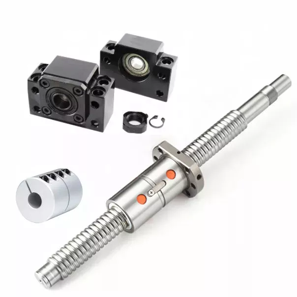
Ball Screws – Dimensions, Applications, and Benefits

Ball screws are popular, lightweight, precision mechanical components. They are commonly used in machinery, gears, and knurled objects. These screw-like parts can be easily maintained and lubricated using oil. This article discusses their dimensions, applications, and benefits. The following sections provide additional information to help you select the right ball screw for your needs. We’ll discuss some of the important characteristics of ball screws and what makes them so useful.
air-compressor

Preloading

A key problem with nut-to-ball screw backlash is the ability of the nut to move freely on the threads of the ball screw. To solve this problem, a patented solution was developed. The patent, 4,557,156, describes an innovative method for preloading ball screws and nuts. By applying a preloading nut, the threads of the ball screw are prevented from moving back and forth with the nut.
A mechanical design that involves axial play involves a lot of mass, inertia, and complexity. These characteristics lead to wear and rust problems. Preloading ball screws using a dynamic system reduces mechanical complexity by allowing preload to be adjusted while the mechanism is running. This also reduces the number of mechanical parts and simplifies manufacturing. Thus, the preloading method of the present invention is advantageous.
The servo motors used in the system monitor the output torque and adjust the power to 1 motor in a dynamic way, thus creating a torque differential between the balls. This torque differential in turn creates a preload force between the ball nuts. The servo motors’ output torque is controlled in this manner, and the machine’s backlash clearance can be precisely controlled. Hence, the machine can perform multiple tasks with increased precision.
Several prior art methods for preloading ball screws are described in detail in FIG. 3. The helical thread grooves of the ball screw 26 and the nut 24 define a pathway for roller balls to travel along. The stylized broken line indicates the general position of the axis of the ball roller screw 26. The corresponding ball screws are used in a number of applications. This technique may be used to manufacture custom-sized screws.

Lubrication

Ball screws are mechanical elements that roll balls through a groove. Improper lubrication can reduce the life of these screw elements. Improper lubrication can lead to shaft damage, malfunction, and decreased performance. This article discusses the importance of proper lubrication and how to do it. You can learn how to properly lubricate ball screws in the following paragraphs. Here are some tips to ensure long-term performance and safety of ball screws.
The first thing you should do is determine the type of lubricant you’ll be using. Oils are preferred because they tend to remain inside the ball nut, and grease can build up in it. Oils also tend to have better anti-corrosion properties than grease. However, grease is more likely to be clogged with debris than oils. So, before you choose the lubricant that’s right for your screw, make sure you wash it off.
The oil used in ball screw lubrication must be applied at a controlled rate. It can prevent metal-on-metal contact and clean out contaminants as it passes through the ball nut. However, oil as a lubricant is expensive and can contaminate the process if it mixes with the cutting fluid. Grease, on the other hand, is inexpensive, requires fewer applications, and does not contaminate process fluids.
If you use a synthetic oil for lubrication, make sure to choose a viscosity that is appropriate for the operating temperature. Oil viscosity can increase the temperature of the ball screw assembly, and excessive oil can reduce its life. A correct amount of oil will reduce the temperature of the ball screw assembly, while too little will increase friction and wear. Use the following guidelines to determine the right amount of oil for your screw.
air-compressor

Dimensions

Dimensions of ball screws are a very important aspect to consider when determining the best type for your application. Technical acceptance conditions for ball screws specify the allowed deviations during acceptance tests. The tolerance class can also change, depending on the needs of a specific application. The following table lists the most important tolerance values for the full range of screw lengths. This table is a helpful guide when looking for a specific screw. The table below lists the dimensions of common ball screws.
The axial load applied to a ball screw is 0.5 x Fpr / 2Fpr. The minimum screw diameter is known as the root diameter. The axial load causes the screw shaft to deform in a certain way (DL1 and DL2). The elastic deflection induced by the load on a ball screw is called its rigidity. This rigidity is important for calculating sizing parameters for a ball screw.
The preload value of the ball screw affects the dynamic load capacity. A preload of 10 percent is considered adequate, while a value greater than this may compromise the screw’s durability. In general, a high preload value will result in a lower dynamic load capacity and greater wear. However, the preload value must be calculated with the relevant screw parameters. This is because a high preload value reduces the screw’s durability.
To ensure that your screw meets the specified parameters, the dynamic load capacity must be calculated. This is the amount of force a ball screw will withstand under a specified load. This calculation also includes strength checks. If you are using a ball screw for applications that need extra strength, it may require a safety factor. For example, if the screw is used for double-axial mounting, then the outer ball nut must be inserted into the nut, causing a secondary load.

Applications

The present invention provides a simple, yet highly effective way to mount a ball screw. Its absence of insert slots or through holes makes it simpler to assemble and provides a more uniform nut. The lack of mechanical features also reduces heat treatment issues, and the nut’s hardness can be uniformly hardened. As a result, the screw’s overall performance is improved. Here are some examples of applications for ball screws.
Preloading is the process of applying force to a ball screw. This increases the rigidity of the screw assembly and eliminates backlash, which is lost motion caused by clearance between the nut and ball. Backlash disrupts repeatability and accuracy. Spacer preloading involves inserting force between 2 ball nuts and transmitting it through the grooves. This method is ideal when preloading is needed in large quantities. In addition to increasing rigidity, preloading can improve accuracy.
Ball screws require careful care in their working surfaces to prevent contamination. Rubber or leather bellows can be used to protect their surfaces, while positive air pressure can be applied to the screw. Preloading eliminates backlash, a common problem among screw assemblies. In addition to the numerous applications for ball screws, they are also critical to computer-controlled motion-control systems and wire bonding. And there are many more examples. So what are the benefits of using these devices?
The spring preloading system uses a spring in between 2 ball nuts, applying tensional forces to the ball nuts. This spring creates grooves in the nut’s middle, which facilitates recirculation of the balls. The spring preloading mechanism is more compact than the double nut mechanism, but the lengthening of the lead reduces the ball screw’s load capacity. Its compact design makes it ideal for small clearance assemblies.
air-compressor

Maintenance

In addition to performing maintenance tasks yourself, the manufacturer of ball screws should offer reverse engineering services that will enable them to identify specific problems. The process of reverse engineering allows ball screw manufacturers to develop new ball screws and parts. In the event that a ball screw is beyond repair, a manufacturer can often save a significant amount of money by repairing it instead of replacing it. In addition to repairing a ball screw, the manufacturer should also offer free evaluation services for the component. Reconditioning and replacement involve the use of new parts, while reloading and replacement replace the screw.
Performing routine maintenance checks on ball screw assemblies is essential for maintaining optimal performance and extending their service life. Overtime, excessive wear can lead to a variety of problems, including backlash, vibration, and ball bearing noise. In addition, the increased friction increases the required torque for turning a screw, causing system failure and significant downtime. To ensure that a ball screw is fully functional, it must be checked for wear and maintain the proper lubrication system.
Discoloration or pitting on a ball screw indicates that it is in need of repair. The same is true if there are chatter marks in the ball groove. Oftentimes, a ball screw needs a new lubrication seal or wipers. Additionally, it may be missing or over-wearing, which could result in permanent failure. Finally, excessive power draw could be a sign of improper lubrication or improper installation.
Proper maintenance is essential for any machine tool. When performed properly, machine tools can last decades with continuous use. Proper care and maintenance is essential to ensure long life and optimal performance. In addition to improving machine tool uptime, proper maintenance affects the accuracy and repeatability of the end product. Therefore, premium machine tool manufacturers focus on the performance and durability of ball screws. They develop innovative designs and lubricants to optimize the lifespan of their products.

China Standard Gearless Tractor Asia CZPT Parts for Elevator Funicular Car     with Best SalesChina Standard Gearless Tractor Asia CZPT Parts for Elevator Funicular Car     with Best Sales

China Best Sales Agricultural Machinery Tractor Tie Rod End OEM 826852m91 907729m1 969352m1 135 240 250 Tractor Spare Parts near me factory

Product Description

Product Description

Warranty  1 Year Certification TS16949
Color Natural color Application Massey Ferguson
OEM NO. 826852M91  MOQ 100 PCS
Engravement Customized Port HangZhou/ZheJiang

Specifications

1.Supply to USA,Europe,and so on
2.Matrial:Body C45 Ball Pin Cr40
3.Professional Perfomance Auto parts supplier

Detail Images

Other Products

Our Company

Packing & Delivery

Certification

Our Service

1. OEM Manufacturing welcome: Product, Package…
2. Sample order
3. We will reply you for your inquiry in 24 hours.
4. after sending, we will track the products for you once every 2 days, until you get the products. When you got the
goods, test them, and give me a feedback.If you have any questions about the problem, contact with us, we will offer
the solve way for you.

FAQ

Q1. What is your terms of packing?
A: Generally, we pack our goods in neutral white boxes and brown cartons. If you have legally registered patent,
we can pack the goods in your branded boxes after getting your authorization letters.

Q2. What is your terms of payment?
A: T/T 30% as deposit, and 70% before delivery. We’ll show you the photos of the products and packages
before you pay the balance.

Q3. What is your terms of delivery?
A: EXW, FOB, CFR, CIF, DDU.

Q4. How about your delivery time?
A: Generally, it will take 30 to 60 days after receiving your advance payment. The specific delivery time depends
on the items and the quantity of your order.

Q5. Can you produce according to the samples?
A: Yes, we can produce by your samples or technical drawings. We can build the molds and fixtures.

Q6. What is your sample policy?
A: We can supply the sample if we have ready parts in stock, but the customers have to pay the sample cost and
the courier cost.

Q7. Do you test all your goods before delivery?
A: Yes, we have 100% test before delivery

Q8: How do you make our business long-term and good relationship?
A:1. We keep good quality and competitive price to ensure our customers benefit ;
2. We respect every customer as our friend and we sincerely do business and make friends with them,
no matter where they come from.

Axle Spindle Types and Features

The axle spindle is an integral part of your vehicle’s suspension. There are several different types and features, including mounting methods, bearings, and functions. Read on for some basic information on axle spindles. The next part of the article will cover how to choose the correct axle spindle for your vehicle. This article will also discuss the different types of spindles available, including the differences between the rear and front bearings.
Driveshaft

Features

The improved axle spindle nut assembly is capable of providing additional performance benefits, including increased tire life and reduced seal failure. Its keyway features and radially inwardly extending teeth allow nut adjustment to be accomplished with precision. The invention further provides a unique, multi-piece locking mechanism that minimizes leakage and torque transfer. Its principles and features are detailed in the appended claims. For example, the improved axle spindle nut assembly is designed for use in vehicles that are equipped with a steering system.
The axle spindle nut assembly includes a nut 252 with threads 256 on its inner periphery. The axle spindle 50 also features threads 198 on its outer periphery. The nut is threaded onto the outboard end of the axle spindle 50 until it contacts the inboard surface of the axle spacer 26. In the assembled state, a bearing spacer 58 is also present on the axle spindle.
The axle spindle nut assembly can reduce axial end play between the wheel end assembly 52 and the axle spindle 50. It can be tightened to an extreme torque level, but if the thread faces separate, it will undercompress the bearing cone and spacer group. To minimize these disadvantages, the axle spindle nut assembly is a critical component of a wheel-end assembly. There are several types of axle spindle nuts.
The third embodiment of the axle spindle nut assembly 300 comprises an inner washer 202, an outer washer 310, and at least 1 screw 320. The axle spindle nut assembly 300 secures and preloads bearing cones 55, 57. Unlike the first embodiment, the axle spindle nut assembly 300 uses the inner washer 202, which is optional in the third embodiment. The inner washer 202 and outer washer 310 are similar to those of the first embodiment.

Functions

An axle spindle is 1 of the most important components of a vehicle’s suspension system. The spindle retains the position of bearings and a spacer in an axle by providing clamp force. The inner nut of an axle spindle should be properly torqued to ensure a secure fit. A spindle nut is also responsible for compressing bearings and spacers. If any of these components are missing, the spindle will not work properly.
An axle spindle is used in rear wheel drive cars. It carries the weight of the vehicle on the axle casing and transfers the torque from the differential to the wheels. The axle spindle and hub are secured on the spindle by large nuts. The axle spindle is a vital component of rear wheel drive vehicles. Hence, it is essential to understand the functions of axle spindle. These components are responsible for the smooth operation of a vehicle’s suspension system.
Axle spindles can be mounted in 3 ways: in the typical axle assembly, the spindles are bolted onto the ends of the tubular axle, and the axle is suspended by springs. Short stub-axle mounting uses a torsion beam that flexes to provide a smooth ride. A second washer is used to prevent excessive rotation of the axle spindle.
Apart from being a crucial component of the suspension system, the spindles of the wheels are responsible for guiding the vehicle in a straight line. They are connected to the steering axis and are used in different types of suspension systems. European cars use a MacPherson Strut suspension system in which the spindle is connected to the arms in the front and rear of the suspension frame. The MacPherson strut allows the shock absorber housing to turn the wheel.
Driveshaft

Methods of mounting

Various methods of mounting axle spindle are available. In general, these methods involve forming a tubular blank of uniform cross section and thickness, and receiving the bearing assembly against it. The spindle is then secured using a collar, which also serves as a bearing stop. In some cases, additional features are used to provide greater security. Some of these features may not be suitable for all applications. But they are generally suitable.
Axle spindle forming is usually done by progressive steps using hollow punches. The metallic body of the punch has an inner work surface, which receives the axle blank. A mandrel is fixed within the work opening of the punch. The punch body’s work surface forges the spindle about the mandrel. The punch has 2 ends, a closed and an open one.
A wheeled vehicle axle assembly (10) includes a cylindrical housing member (12 a) and a plurality of spindle mounting flanges (30) secured on the housing member. The spindles (16) are firmly attached to the housing member by means of coupling members. The coupling members are configured to distribute the bending loads imposed on the spindle by the axle. It is important to note that the coupling members can be either threaded or screwed.
Traditionally, axle spindles were made from tubular blanks of irregular thickness. This method allowed for a gradual reduction in diameter and eliminated the need for extra metal within the spindle. Similarly, axles made by cold forming eliminate the need for additional metal in the spindle. In this way, the overall cost of manufacture is also reduced. The material used for manufacturing axles also determines the size and shape of the final product.
Driveshaft

Bearings

A nut 16 is used to retain the wheel bearings on axle spindle 12. The nut comprises several parts. The first portion includes a plurality of threads and a deformable second portion. The nut may be disposed on the inboard or outboard end of the axle spindle. This type of nut is typically secured to the axle spindle by a retaining nut.
The bearings are installed in the spindle to allow the wheel hub to rotate. While bearings are greased, they can dry out over time. Consequently, you may hear a loud clicking sound when turning your vehicle. Alternatively, you may notice grease on the edges of your tires. Bearing failure can cause severe damage to your axle spindle. If you notice any of these symptoms, you may need to replace the bearings on your axle spindle. Fortunately, you can purchase the necessary bearing parts at O’Reilly Auto Parts.
There are 3 ways to mount an axle spindle. A typical axle assembly has the spindles bolted to the ends of the tubular axle. A torsion beam is also used to mount the spindles on the axle. This torsion beam acts like a spring to help make the ride smooth and bump-free. Lastly, the axle spindle is sometimes mounted as a bolt-on component.

Cost

If your axle spindle has been damaged, you may need to have it replaced. This part of the axle is relatively easy to replace, but you need to know how to do it correctly. To replace your axle spindle, you must first remove the damaged one. To do this, a technician will cut the weld. They will then thread the new 1 into the axle tube and torque it to specification. After that, they will weld the new axle spindle into place.
When you are thinking about the cost of an axle spindle replacement, you must first determine if it is worth it for your vehicle. It is generally a good idea to replace the spindle only if it is causing damage to your vehicle. You can also replace your axle housing if it is deteriorating. If you do not replace the spindle, you can risk damaging the axle housing. To save money, you can consider using a repair kit.
You can also purchase an axle nut socket set. Most wrenches have an adjusting socket for this purpose. The socket set should be suitable for most vehicle types. Axle spindle replacement costs around $500 to $600 before tax. However, you should be aware that these costs vary widely based on the type of vehicle you have. The parts can cost between $430 and $480, and the labor can cost anywhere from $50 to 70.

China Best Sales Agricultural Machinery Tractor Tie Rod End OEM 826852m91 907729m1 969352m1 135 240 250 Tractor Spare Parts     near me factory China Best Sales Agricultural Machinery Tractor Tie Rod End OEM 826852m91 907729m1 969352m1 135 240 250 Tractor Spare Parts     near me factory

China Best Sales Speed Reducer Gearbox Tractor Parts for Agricultural Equipment with Free Design Custom

Product Description

Speed Reducer Gearbox Tractor Parts For Agricultural Equipment

Our helical agricultural gearbox has many items for your choosing and we can produce as per your drawing or sample to meet your special request
1. Large output torque
2. Safe, reliable, economical and durable
3. Stable transmission, quiet operation
4. High carrying ability
5. High modularization design, may equip with various outer power input conveniently. Same machine type may equip with various power motor. It is easy to realize the combination and junction between every machine type
6. Transmission ratio: Fine division, wide scope. The combined machine type may form very large transmission ratio, i. E. Output very low rotary speed.
7. Form of installation: The position to be installed is not limited.
8. High strength, compact the box body of high strength cast iron, gear and gear shaft adapts the gas carbonization, quenching and fine grinding process, therefore the bearing capacity of unit volume is high.
9. Long life: Under the condition of correct type chosen(including choosing suitable operation parament ) normal operation and maintenance, the life if main parts speed reducer(except wearing parts)should not be less than 20000 hours. The wearing parts include lubricating oil, oil seal and bearing.
10. Low noise: Because main parts of speed reducer are processed, and tested critically, therefore the noise of speed reducer is low.
11. Parallel axis-bevel wheel speed-down motor.
See the below features:
Size: 40mm—160mm
Reduction ratio: 3 — 512
Torque transmission: 5 Nm — 8 95 Nm
Precision backlash: ≤ 5arcmin
Running noise: 51 70 dB (A)
You are welcome to send us detail enquiry by e-mail or fax.
We can also supply Gearbox, agricultural gearbox, planetary gearbox, worm gearbox, flender gearbox, marine gearbox, gearbox, reduction gearbox, transmission gearbox, gearbox, mower gearbox, rotary cutter gearbox, small transmission gearbox, gearbox for conveyor, bevel gearbox, helical gearbox, swing gearbox, variable speed gearbox, differential gearbox, small planetary gearbox, reducer gearbox, tiller gearbox, pto gearbox, gearbox reducer, hollow shaft gearbox, speed reduction gearbox, industrial gearbox, planetary reduction gearbox, lawn mower gearbox, rotary tiller gearbox, gearbox transmission, worm reduction gearbox, aluminum gearbox, forklift gearbox, nmrv 075 worm gearbox, nmrv030 worm gearbox, shaft mounted gearbox, nmrv 050 worm gearbox, gearbox for agricultural machinery, power tiller gearbox, manual worm gearbox, spiral bevel gearbox, nmrv gearbox, worm wheel gearbox, reduce speed gearbox, industrial transmission gearbox, worm reducer gearbox, gearbox rpm reducer, helical gearbox reducer, wheel planetary gearbox, nmrv040 worm gearbox, worm gearbox reducer, nmrv worm gearbox, aluminium worm gearbox, gearbox reduction, rv series worm gearbox, worm speed gearbox, nmrv050 worm gearbox, gear reducer, worm gear reducer, helical gear reducer, gear speed reducer, worm gear speed reducer, shaft mounted gear reducer, planetary gear reducer, helical gear speed reducer, worm gear wheel reducer, speed gear reducer, bevel gear reducer, planetary gear speed reducer, spur gear reducer, aluminum worm gear reduce, nmrv worm gear reducers, helical-worm gear reducer, helical bevel gear reducers, high speed gear reducer, gear speed reducers, industrial gear reducer, high torque gear reducers

HangZhou CZPT Industry Co., Ltd. is a specialized supplier of a full range of chains, sprockets, gears, gear racks, v belt pulley, timing pulley, V-belts, couplings, machined parts and so on.

Due to our sincerity in offering best service to our clients, understanding of your needs and overriding sense of responsibility toward filling ordering requirements, we have obtained the trust of buyers worldwide. Having accumulated precious experience in cooperating with foreign customers, our products are selling well in the American, European, South American and Asian markets. Our products are manufactured by modern computerized machinery and equipment. Meanwhile, our products are manufactured according to high quality standards, and complying with the international advanced standard criteria.

With many years’ experience in this line, we will be trusted by our advantages in competitive price, one-time delivery, prompt response, on-hand engineering support and good after-sales services.

Additionally, all our production procedures are in compliance with ISO9001 standards. We also can design and make non-standard products to meet customers’ special requirements. Quality and credit are the bases that make a corporation alive. We will provide best services and high quality products with all sincerity. If you need any information or samples, please contact us and you will have our soon reply.

FAQ:
Q1: Are you trading company or manufacturer ?
A: We are factory.

Q2: How long is your delivery time and shipment?
1.Sample Lead-times: generally 10 workdays.
2.Production Lead-times: 20-40 workdays after getting your deposit.

Q3. What is your terms of payment?
A: T/T 30% as deposit, and 70% before delivery.

Q4: What is your advantages?
1. Manufacturer,the most competitive price and good quality.
2. Perfect technical engineers give you the best support.
3. OEM is available.
4. Rich stock and quick delivery.

Q5. If you can’t find the product on our website,what do you next?
Please send us inquiry with product pictures and drawings by email or other ways and we’ll check.


Spiral Gears for Right-Angle Right-Hand Drives

Spiral gears are used in mechanical systems to transmit torque. The bevel gear is a particular type of spiral gear. It is made up of 2 gears that mesh with 1 another. Both gears are connected by a bearing. The 2 gears must be in mesh alignment so that the negative thrust will push them together. If axial play occurs in the bearing, the mesh will have no backlash. Moreover, the design of the spiral gear is based on geometrical tooth forms.
Gear

Equations for spiral gear

The theory of divergence requires that the pitch cone radii of the pinion and gear be skewed in different directions. This is done by increasing the slope of the convex surface of the gear’s tooth and decreasing the slope of the concave surface of the pinion’s tooth. The pinion is a ring-shaped wheel with a central bore and a plurality of transverse axes that are offset from the axis of the spiral teeth.
Spiral bevel gears have a helical tooth flank. The spiral is consistent with the cutter curve. The spiral angle b is equal to the pitch cone’s genatrix element. The mean spiral angle bm is the angle between the genatrix element and the tooth flank. The equations in Table 2 are specific for the Spread Blade and Single Side gears from Gleason.
The tooth flank equation of a logarithmic spiral bevel gear is derived using the formation mechanism of the tooth flanks. The tangential contact force and the normal pressure angle of the logarithmic spiral bevel gear were found to be about 20 degrees and 35 degrees respectively. These 2 types of motion equations were used to solve the problems that arise in determining the transmission stationary. While the theory of logarithmic spiral bevel gear meshing is still in its infancy, it does provide a good starting point for understanding how it works.
This geometry has many different solutions. However, the main 2 are defined by the root angle of the gear and pinion and the diameter of the spiral gear. The latter is a difficult 1 to constrain. A 3D sketch of a bevel gear tooth is used as a reference. The radii of the tooth space profile are defined by end point constraints placed on the bottom corners of the tooth space. Then, the radii of the gear tooth are determined by the angle.
The cone distance Am of a spiral gear is also known as the tooth geometry. The cone distance should correlate with the various sections of the cutter path. The cone distance range Am must be able to correlate with the pressure angle of the flanks. The base radii of a bevel gear need not be defined, but this geometry should be considered if the bevel gear does not have a hypoid offset. When developing the tooth geometry of a spiral bevel gear, the first step is to convert the terminology to pinion instead of gear.
The normal system is more convenient for manufacturing helical gears. In addition, the helical gears must be the same helix angle. The opposite hand helical gears must mesh with each other. Likewise, the profile-shifted screw gears need more complex meshing. This gear pair can be manufactured in a similar way to a spur gear. Further, the calculations for the meshing of helical gears are presented in Table 7-1.
Gear

Design of spiral bevel gears

A proposed design of spiral bevel gears utilizes a function-to-form mapping method to determine the tooth surface geometry. This solid model is then tested with a surface deviation method to determine whether it is accurate. Compared to other right-angle gear types, spiral bevel gears are more efficient and compact. CZPT Gear Company gears comply with AGMA standards. A higher quality spiral bevel gear set achieves 99% efficiency.
A geometric meshing pair based on geometric elements is proposed and analyzed for spiral bevel gears. This approach can provide high contact strength and is insensitive to shaft angle misalignment. Geometric elements of spiral bevel gears are modeled and discussed. Contact patterns are investigated, as well as the effect of misalignment on the load capacity. In addition, a prototype of the design is fabricated and rolling tests are conducted to verify its accuracy.
The 3 basic elements of a spiral bevel gear are the pinion-gear pair, the input and output shafts, and the auxiliary flank. The input and output shafts are in torsion, the pinion-gear pair is in torsional rigidity, and the system elasticity is small. These factors make spiral bevel gears ideal for meshing impact. To improve meshing impact, a mathematical model is developed using the tool parameters and initial machine settings.
In recent years, several advances in manufacturing technology have been made to produce high-performance spiral bevel gears. Researchers such as Ding et al. optimized the machine settings and cutter blade profiles to eliminate tooth edge contact, and the result was an accurate and large spiral bevel gear. In fact, this process is still used today for the manufacturing of spiral bevel gears. If you are interested in this technology, you should read on!
The design of spiral bevel gears is complex and intricate, requiring the skills of expert machinists. Spiral bevel gears are the state of the art for transferring power from 1 system to another. Although spiral bevel gears were once difficult to manufacture, they are now common and widely used in many applications. In fact, spiral bevel gears are the gold standard for right-angle power transfer.While conventional bevel gear machinery can be used to manufacture spiral bevel gears, it is very complex to produce double bevel gears. The double spiral bevel gearset is not machinable with traditional bevel gear machinery. Consequently, novel manufacturing methods have been developed. An additive manufacturing method was used to create a prototype for a double spiral bevel gearset, and the manufacture of a multi-axis CNC machine center will follow.
Spiral bevel gears are critical components of helicopters and aerospace power plants. Their durability, endurance, and meshing performance are crucial for safety. Many researchers have turned to spiral bevel gears to address these issues. One challenge is to reduce noise, improve the transmission efficiency, and increase their endurance. For this reason, spiral bevel gears can be smaller in diameter than straight bevel gears. If you are interested in spiral bevel gears, check out this article.
Gear

Limitations to geometrically obtained tooth forms

The geometrically obtained tooth forms of a spiral gear can be calculated from a nonlinear programming problem. The tooth approach Z is the linear displacement error along the contact normal. It can be calculated using the formula given in Eq. (23) with a few additional parameters. However, the result is not accurate for small loads because the signal-to-noise ratio of the strain signal is small.
Geometrically obtained tooth forms can lead to line and point contact tooth forms. However, they have their limits when the tooth bodies invade the geometrically obtained tooth form. This is called interference of tooth profiles. While this limit can be overcome by several other methods, the geometrically obtained tooth forms are limited by the mesh and strength of the teeth. They can only be used when the meshing of the gear is adequate and the relative motion is sufficient.
During the tooth profile measurement, the relative position between the gear and the LTS will constantly change. The sensor mounting surface should be parallel to the rotational axis. The actual orientation of the sensor may differ from this ideal. This may be due to geometrical tolerances of the gear shaft support and the platform. However, this effect is minimal and is not a serious problem. So, it is possible to obtain the geometrically obtained tooth forms of spiral gear without undergoing expensive experimental procedures.
The measurement process of geometrically obtained tooth forms of a spiral gear is based on an ideal involute profile generated from the optical measurements of 1 end of the gear. This profile is assumed to be almost perfect based on the general orientation of the LTS and the rotation axis. There are small deviations in the pitch and yaw angles. Lower and upper bounds are determined as – 10 and -10 degrees respectively.
The tooth forms of a spiral gear are derived from replacement spur toothing. However, the tooth shape of a spiral gear is still subject to various limitations. In addition to the tooth shape, the pitch diameter also affects the angular backlash. The values of these 2 parameters vary for each gear in a mesh. They are related by the transmission ratio. Once this is understood, it is possible to create a gear with a corresponding tooth shape.
As the length and transverse base pitch of a spiral gear are the same, the helix angle of each profile is equal. This is crucial for engagement. An imperfect base pitch results in an uneven load sharing between the gear teeth, which leads to higher than nominal loads in some teeth. This leads to amplitude modulated vibrations and noise. In addition, the boundary point of the root fillet and involute could be reduced or eliminate contact before the tip diameter.

China Best Sales Speed Reducer Gearbox Tractor Parts for Agricultural Equipment     with Free Design CustomChina Best Sales Speed Reducer Gearbox Tractor Parts for Agricultural Equipment     with Free Design Custom

China Best Sales OEM Custom Ductile Iron Sand Casting Part Tractor Part/Metal Sand Machinery/Machined Steel /Mechanical/Motor/Casting/Cast/ Parts for Compressor Body with Best Sales

Product Description

OEM Custom GGG40 Ductile Iron Sand Casting Part

Product description :
 

Item Name
 
OEM Custom GGG40 Ductile Iron Sand Casting Part 
 General Products      
 Application/Service Area
 
Metal Parts Solution for Vehicle, Agriculture machine, Construction Machine, transportation equipment, Valve and Pump system, Agriculture machine metal Parts, engine bracket, truck chassis bracket, gear box , gear housing , gear cover, shaft, spline shaft , pulley, flange, connection pipe, pipe, hydraulic valve , valve housing ,Fitting , flange, wheel, fly wheel, oil pump housing, starter housing, coolant pump housing, transmission shaft , transmission gear, sprocket, chains etc.
 
 Main blank Process for Casting  
Sand Casting , Resin Sand Casting, Green Sand Casting, Shell Molding, Automatic Molding, Lost Wax Casting, Lost Foam Molding Casting
 
 Blanks Tolerance -Casting  Tolerance CT9-10 for  Machine Molding Process,
CT8-9 for Shell Molding and Lost Foam Molding Casting Process
CT10-11 for Manual Molding Sand  casting Process
 Applicable Material  
See Table Below (Ductile Iron Casting, Grey Iron Casting)
OR According to customer requirement
 
 Casting Blank Size  /Dimensions 2 mm-2000mm / 0.08inch-79inch  for casting iron, according to customer requirement
 Casting Blank Weight Range from 0.01kg-1000kg for casting iron
 Applicable Machining Process  
CNC Machining/ Lathing/ Milling/ Turning/ Boring/ Drilling/ Tapping/ Broaching/Reaming /Grinding/Honing and  etc.
 
 Machining Tolerance From 0.005mm-0.01mm-0.1mm
 Machined Surface Quality Ra 0.8-Ra3.2, according to customer requirement
 Applicable Heat Treatment  
Normalization , annealing, quenching and tempering, Case Hardening, Nitriding, Carbon Nitriding, Induction Quenching
 
 Applicable Finish Surface  Treatment  
Shot/sand blast, polishing, Surface passivation, Primer Painting , Powder coating, ED- Coating, Chromate Plating, zinc-plate, Dacromat coating, Finish Painting.
 
 MOQ For iron casting : 100pcs
For Machining : 50pcs
 Lead Time 45days from the receipt date of deposit for ductile iron casting

Company Introduction :

ZheJiang CZPT International Trading Company is a trading company which is specialized in castings,

forgings and machinery parts.

Our products include all kinds of raw castings to be made of ductile iron , grey iron , brass , stainless

steel and aluminums, machined castings and forged parts . To make these parts according to the

customers’ drawings , we have relative suitable production craft and equipments, such as resin sand ,

sand CZPT , hot core boxes , lost-wax , lost  foam and so on .

Specially for hydrant bodies and valves’ bodies, we have collected rich experience for these products in

the past 16 year’s actual production, Now we are proud of our products with good surface and high

quality material. Whatever,we have been trying our best to provide our customers with better quality

castings by improving  production crafts and more careful quality control.

Looking Forward To Receiving Your Kind Favorable Reply At Your Earliest!
 

Screw Shaft Types

A screw shaft is a cylindrical part that turns. Depending on its size, it is able to drive many different types of devices. The following information outlines the different types of screws, including their sizes, material, function, and applications. To help you select the right screw shaft, consider the following factors:
screwshaft

Size

A screw can come in a variety of shapes and sizes, ranging from a quarter to a quarter-inch in diameter. A screw is a cylindrical shaft with an inclined plane wrapped around it, and its main function is to fasten objects together by translating torque into a linear force. This article will discuss the dimensions of screws and how to determine the size of a screw. It is important to note that screw sizes can be large and small depending on the purpose.
The diameter of a screw is the diameter of its shaft, and it must match the inner diameter of its nuts and washers. Screws of a certain diameter are also called machine screws, and they can be larger or smaller. Screw diameters are measured on the shaft underneath the screw head. The American Society of Mechanical Engineers (ASME) standardized screw diameters in 3/50-inch to 16 (3/8-inch) inches, and more recently, sizes were added in U.S. fractions of an inch. While shaft and head diameters are standardized, screw length may vary from job to job.
In the case of the 2.3-mm screw group, the construct strength was not improved by the 1.2-mm group. The smaller screw size did not increase the strength of the construct. Further, ABS material did not improve the construct strength. Thus, the size of screw shaft is an important consideration in model design. And remember that the more complex your model is, the larger it will be. A screw of a given size will have a similar failure rate as a screw of a different diameter.
Although different screw sizes are widely used, the differences in screw size were not statistically significant. Although there are some limitations, screws of different sizes are generally sufficient for fixation of a metacarpal shaft fracture. However, further clinical studies are needed to compare screw sizes for fracture union rates. So, if you are unsure of what size of screw shaft you need for your case, make sure to check the metric chart and ensure you use the right one.
screwshaft

Material

The material of a screw shaft plays an important role in the overall performance of a screw. Axial and central forces act to apply torque to the screw, while external forces, such as friction, exert a bending moment. The torsional moments are reflected in the torque, and this causes the screw to rotate at a higher rate than necessary. To ensure the longevity of the screw, the material of the screw shaft should be able to handle the bending moment, while the diameter of the shaft should be small enough to avoid causing damage.
Screws are made from different metals, such as steel, brass, titanium, and bronze. Manufacturers often apply a top coating of chromium, brass, or zinc to improve corrosion resistance. Screws made of aluminum are not durable and are prone to rusting due to exposure to weather conditions. The majority of screw shafts are self-locking. They are suited for many applications, including threaded fasteners, C-clamps, and vises.
Screws that are fabricated with conical sections typically feature reduced open cross-sectional areas at the discharge point. This is a key design parameter of conical screw shafts. In fact, reductions of up to 72% are common across a variety of applications. If the screw is designed to have a hard-iron hanger bearing, it must be hardened. If the screw shaft is not hardened, it will require an additional lubricant.
Another consideration is the threads. Screw shafts are typically made of high-precision threads and ridges. These are manufactured on lathes and CNC machines. Different shapes require different materials. Materials for the screw shaft vary. There are many different sizes and shapes available, and each 1 has its own application. In addition to helical and conical screw shafts, different materials are also available. When choosing material, the best 1 depends on the application.
The life of the screw depends on its size, load, and design. In general, the material of the screw shaft, nut body, and balls and rollers determine its fatigue life. This affects the overall life of the screw. To determine whether a specific screw has a longer or shorter life, the manufacturer must consider these factors, as well as the application requirements. The material should be clean and free of imperfections. It should be smooth and free of cracks or flaking, which may result in premature failure.

Function

The function of a screw shaft is to facilitate the rotation of a screw. Screws have several thread forms, including single-start, double-start and multi-start. Each form has its own advantages and disadvantages. In this article we’ll explore each of them in detail. The function of a screw shaft can vary based on its design, but the following are common types. Here are some examples of screw shaft types and their purposes.
The screw’s torque enables it to lift objects. It can be used in conjunction with a bolt and nut to lift a load. Screws are also used to secure objects together. You can use them in screw presses, vises, and screw jacks. But their primary function is to hold objects together. Listed below are some of their main functions. When used to lift heavy loads, they can provide the required force to secure an object.
Screws can be classified into 2 types: square and round. Square threads are more efficient than round ones because they apply 0deg of angle to the nut. Square threads are also stronger than round threads and are often used in high-load applications. They’re generally cheaper to manufacture and are more difficult to break. And unlike square threads, which have a 0deg thread angle, these threads can’t be broken easily with a screwdriver.
A screw’s head is made of a series of spiral-like structures that extend from a cylindrical part to a tip. This portion of the screw is called the shank and is made of the smallest area. The shank is the portion that applies more force to the object. As the shaft extends from the head, it becomes thinner and narrow, forming a pointed tip. The head is the most important part of the screw, so it needs to be strong to perform its function.
The diameter of the screw shaft is measured in millimeters. The M8 screw has a thread pitch of 1.25 mm. Generally, the size of the screw shaft is indicated by the major and minor diameter. These dimensions are appended with a multiplication sign (M8x1).
screwshaft

Applications

The design of screws, including their size and shape, determines their critical rotating speeds. These speeds depend on the threaded part of the screw, the helix angle, and the geometry of the contact surfaces. When applied to a screw, these limits are referred to as “permissible speed limits.” These maximum speeds are meant for short periods of time and optimized running conditions. Continuous operation at these speeds can reduce the calculated life of a nut mechanism.
The main materials used to manufacture screws and screw shafts include steel, stainless steel, titanium, bronze, and brass. Screws may be coated for corrosion resistance, or they may be made of aluminium. Some materials can be threaded, including Teflon and nylon. Screw threads can even be molded into glass or porcelain. For the most part, steel and stainless steel are the most common materials for screw shafts. Depending on the purpose, a screw will be made of a material that is suitable for the application.
In addition to being used in fasteners, screw shafts are used in micrometers, drillers, conveyor belts, and helicopter blades. There are numerous applications of screw shafts, from weighing scales to measuring lengths. If you’re in the market for a screw, make sure to check out these applications. You’ll be happy you did! They can help you get the job done faster. So, don’t delay your next project.
If you’re interested in learning about screw sizing, then it’s important to know the axial and moment loads that your screws will experience. By following the laws of mechanics and knowing the load you can calculate the nominal life of your screw. You can also consider the effect of misalignment, uneven loading, and shocks on your screw. These will all affect the life of your screw. Then, you can select the right screw.

China Best Sales OEM Custom Ductile Iron Sand Casting Part Tractor Part/Metal Sand Machinery/Machined Steel /Mechanical/Motor/Casting/Cast/ Parts for Compressor Body     with Best SalesChina Best Sales OEM Custom Ductile Iron Sand Casting Part Tractor Part/Metal Sand Machinery/Machined Steel /Mechanical/Motor/Casting/Cast/ Parts for Compressor Body     with Best Sales

China Best Sales High Quality Cast Iron Parts for Tractor near me shop

Product Description

  Sand Casting /Grey iron sand casting/Ductile Iron Casting/steel casting

  Product description
 

Description OEM grey and ductile iron casting from Chinese factory
Casting process precoated sand casting/precision casting/shell mold casting
Material Gey iron casting of GG15.GG20.GG25.GG30.GG35, Ductile iron casting of GGG40-,GGG50,GGG60,GGG70,GGG80, QT400-18QT450-10QT500-7QT600-3
Certificate TS16949,SGS
Brand   RSIN
Surface Paint in Black, grey or red according to customer’s requirment,KTL
Machined by CNC Vertical lathe and CNC machining center
Packing Wooden pallet
Balance test  Available
Application Automative, pump and valve, other machinery part

 
Company Introduction

1. Busines type: manufacturer with foundry and machining shop
2  Our products: brake drum and wheel hub, other cast iron sand castings.
3. Factory size: more than 120,000 square meters,
4. Number of employees:  around 300 employee
5Year established: since  2007
6. Production capacity: 20000T/Year
7. Certification:  TS16949, SGS.
8. Customers:  Axle manufacturer,  truck and semi tractor manufactuer, and other machinery parts
9. Casting method: Iron based precoated sand casting and precoated shell casting.

Our Advantages:

(1)    Competitive price, all products are casted and machined in our factory, shipped directly to customer.
(2)    Reliable quality,  TS16946 certified casting manufacturer, we have strict control about quality.
(3)    Professional, we focus on production of heavy duty truck & trailer wheel hub and brake drum for more than 10 years.
(4)    Fast shipment,  we have a efficient management system, several automatic casting lines, and more than 10 machining lines.
(5)    Excellent service, our sales team has more than 10 years’ experience in oversea market, we know you better.
(6)    Flexible production, we can customize the product according to your drawing.

Introduction of  casting process:

Our casting process is the iron based  precoated sand casting and shell mold sand casting, with this method, a smooth casting surface can be achived For the iron based precoated sand casting, The inner quality is better because of the shock chill of the iron mold.

   There are other  types of casting method in different foundries, such as low wax casting, precision silican casting, lost foam casting, vaccum casting, resin sand casting, green sand casting, clay sand casting.centrifugal casting. powder casting, die casting.  Different method require different moulding sand, and casting surface and inner quality is different according to different moulding sand. 

   According the material, there are grey iron sand casting, ductile iron sand casting, stainless steel casting, carbon steel casting, high Mn steel casting, bronze casting, aluminum casting.

   Different size ,weight, quantity and material of the castings should use differrent casting method.  Small size and weight stainless steel casting should use the precision silican casting or lost wax casting to get good dimension and outlooking.  Big part and small quantity can choose green sand casting and clay sand casting, the cost will be lower. For batch quantity and small size aluminum can use die casting, fast, good looking and good quality. 

     Contact us for more information,  we are professional and can customize your requirment according to your drawing, and we have  experienced engineers to analyse  your drawing and give you best soltuion.

Factory View

Test Equipment

     Certificates

With our customers

         FAQ                 
1. Are you a factory or trading company? 
We are a TS16949 and IGS certified factory specilizing in producing brake drum and wheel hub and other castings. We cast and machine the parts for more than 10 years.

2. Can you customize the parts according to the drawing?

We have professional technical dept, We are CZPT to customize your parts according to the drawings. 

3. Can you supply samples?

We can supply the samples for free, but you need to bear the delivery cost.

4. Do you have a min order quantity?
We don’t have a min order quantity, we can send you the parts if we have stock.  

5. What is the  period of sample production?

 It will take 45 days to develop new product.                


Contact me 

What You Should Know About Axle Shafts

There are several things you should know about axle shafts. These include what materials they’re made of, how they’re constructed, and the signs of wear and tear. Read on to learn more about axle shafts and how to properly maintain them. Axle shafts are a crucial part of any vehicle. But how can you tell if 1 is worn out? Here are some tips that can help you determine whether it’s time to replace it.

Materials used for axle shafts

When it comes to materials used in axle shafts, there are 2 common types of materials. One is carbon fiber, which is relatively uncommon for linear applications. Carbon fiber shafting is produced by CZPT(r). The main benefit of carbon fiber shafting is its ultra-low weight. A carbon fiber shaft of 20mm diameter weighs just 0.17kg, as opposed to 2.46kg for a steel shaft of the same size.
The other type of material used in axle shafts is forged steel. This material is strong, but it is difficult to machine. The resulting material has residual stresses, voids, and hard spots that make it unsuitable for some applications. A forged steel shaft will not be able to be refinished to its original dimensions. In such cases, the shaft must be machined down to reduce the material’s hardness.
Alternatively, you can choose to purchase a through-hardened shaft. These types of axle shafts are suitable for light cars and those that use single bearings on their hub. However, the increased diameter of the axle shaft will result in less resistance to shock loads and torsional forces. For these applications, it is best to use medium-carbon alloy steel (MCA), which contains nickel and chromium. In addition, you may also need to jack up your vehicle to replace the axle shaft.
The spline features of the axle shaft must mate with the spline feature on the axle assembly. The spline feature has a slight curve that optimizes contact surface area and distribution of load. The process involves hobbing and rolling, and it requires special tooling to form this profile. However, it is important to note that an axle shaft with a cut spline will have a 30% smaller diameter than the corresponding 1 with an involute profile.
Another common material is the 300M alloy, which is a modified 4340 chromoly. This alloy provides additional strength, but is more prone to cracking. For this reason, this alloy isn’t suited for street-driven vehicles. Axle shafts made from this alloy are magnaflushed to detect cracks before they cause catastrophic failure. This heat treatment is not as effective as the other materials, but it is still a good choice for axle shafts.
Driveshaft

Construction

There are 3 basic types of axle shafts: fully floating, three-quarter floating, and semi-floating. Depending on how the shaft is used, the axles can be either stationary or fully floating. Fully floating axle shafts are most common, but there are exceptions. Axle shafts may also be floating or stationary, or they may be fixed. When they are stationary, they are known as non-floating axles.
Different alloys have different properties. High-carbon steels are harder than low-carbon steels, while medium-carbon steels are less ductile. Medium-carbon steel is often used in axle shafts. Some shafts contain additional metals, including silicon, nickel, and copper, for case hardening. High-carbon steels are preferred over low-carbon steels. Axle shafts with high carbon content often have better heat-treatability than OE ones.
A semi-floating axle shaft has a single bearing between the hub and casing, relieving the main shear stress on the shaft but must still withstand other stresses. A half shaft needs to withstand bending loads from side thrust during cornering while transmitting driving torque. A three-quarter floating axle shaft is typically fitted to commercial vehicles that are more capable of handling higher axle loads and torque. However, it is possible to replace or upgrade the axle shaft with a replacement axle shaft, but this will require jacking the vehicle and removing the studs.
A half-floating axle is an alternative to a fixed-length rear axle. This axle design is ideal for mid-size trucks. It supports the weight of the mid-size truck and may support mid-size trucks with high towing capacities. The axle housing supports the inner end of the axle and also takes up the end thrust from the vehicle’s tires. A three-quarter floating axle, on the other hand, is a complex type that is not as simple as a semi-floating axle.
Axle shafts are heavy-duty load-bearing components that transmit rotational force from the rear differential gearbox to the rear wheels. The half shaft and the axle casing support the road wheel. Below is a diagram of different forces that can occur in the axle assembly depending on operating conditions. The total weight of the vehicle’s rear can exert a bending action on the half shaft, and the overhanging section of the shaft can be subject to a shearing force.
Driveshaft

Symptoms of wear out

The constant velocity axle, also called the half shaft, transmits power from the transmission to the wheels, allowing the vehicle to move forward. When it fails, it can result in many problems. Here are 4 common symptoms of a bad CV axle:
Bad vibrations: If you notice any sort of abnormal vibration while driving, this may be a sign of axle damage. Vibrations may accompany a strange noise coming from under the vehicle. You may also notice tire wobble. It is important to repair this problem as it could be harmful to your car’s handling and comfort. A damaged axle is generally accompanied by other problems, including a weak braking response.
A creaking or popping sound: If you hear this noise when turning your vehicle, you probably have a worn out CV axle. When the CV joints lose their balance, the driveshaft is no longer supported by the U-joints. This can cause a lot of vibrations, which can reduce your vehicle’s comfort and safety. Fortunately, there are easy ways to check for worn CV axles.
CV joints: A CV joint is located at each end of the axle shaft. In front-wheel drive vehicles, there are 2 CV joints, 1 on each axle. The outer CV joint connects the axle shaft to the wheel and experiences more movement. In fact, the CV joints are only as good as the boot. The most common symptoms of a failed CV joint include clicking and popping noises while turning or when accelerating.
CV joint: Oftentimes, CV joints wear out half of the axle shaft. While repairing a CV joint is a viable repair, it is more expensive than replacing the axle. In most cases, you should replace the CV joint. Replacement will save you time and money. ACV joints are a vital part of your vehicle’s drivetrain. Even if they are worn, they should be checked if they are loose.
Unresponsive acceleration: The vehicle may be jerky, shuddering, or slipping. This could be caused by a bent axle. The problem may be a loose U-joint or center bearing, and you should have your vehicle inspected immediately by a qualified mechanic. If you notice jerkiness, have a mechanic check the CV joints and other components of the vehicle. If these components are not working properly, the vehicle may be dangerous.
Driveshaft

Maintenance

There are several points of concern regarding the maintenance of axle shafts. It is imperative to check the axle for any damage and to lubricate it. If it is clean, it may be lubricated and is working properly. If not, it will require replacement. The CV boots need to be replaced. A broken axle shaft can result in catastrophic damage to the transmission or even cause an accident. Fortunately, there are several simple ways to maintain the axle shaft.
In addition to oil changes, it is important to check the differential lube level. Some differentials need cleaning or repacking every so often. CZPT Moreno Valley, CA technicians know how to inspect and maintain axles, and they can help you determine if a problem is affecting your vehicle’s performance. Some common signs of axle problems include excessive vibrations, clunking, and a high-pitched howling noise.
If you’ve noticed any of these warning signs, contact your vehicle’s manufacturer. Most manufacturers offer service for their axles. If it’s too rusted or damaged, they’ll replace it for you for free. If you’re in doubt, you can take it to a service center for a repair. They’ll be happy to assist you in any aspect of your vehicle’s maintenance. It’s never too early to begin.
CZPT Moreno Valley, CA technicians are well-versed in the repair of axles and differentials. The CV joint, which connects the car’s transmission to the rear wheels, is responsible for transferring the power from the engine to the wheels. Aside from the CV joint, there are also protective boots on both ends of the axle shaft. The protective boots can tear with age or use. When they tear, they allow grease and debris to escape and get into the joint.
While the CV joint is the most obvious place to replace it, this isn’t a time to ignore this important component. Taking care of the CV joint will protect your car from costly breakdowns at the track. While servicing half shafts can help prevent costly replacement of CV joints, it’s best to do it once a season or halfway through the season. ACV joints are essential for your car’s safety and function.

China Best Sales High Quality Cast Iron Parts for Tractor     near me shop China Best Sales High Quality Cast Iron Parts for Tractor     near me shop