Product Description
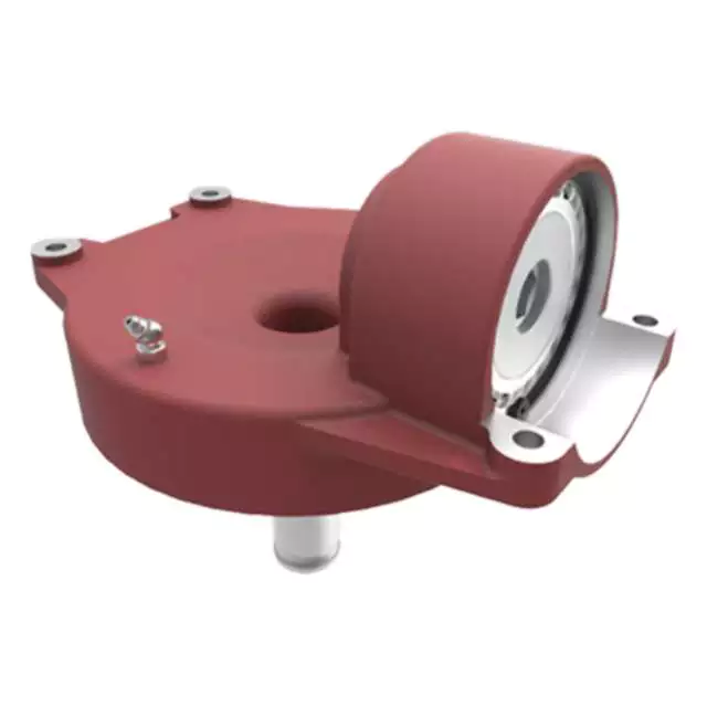
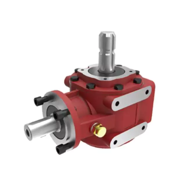
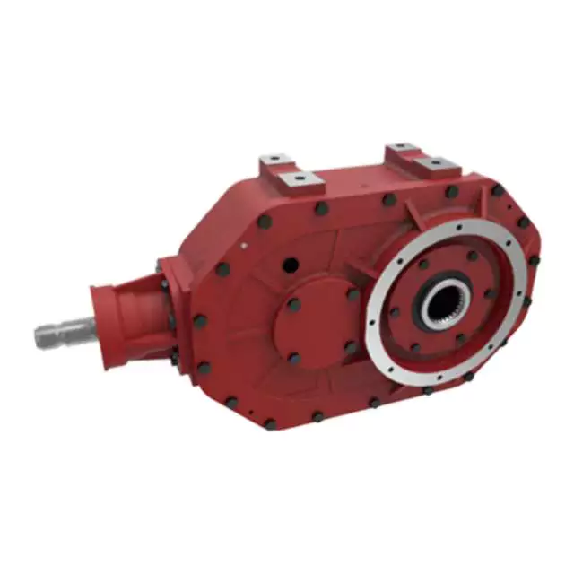
Power Tiller Gear Box Rotary Cultivator Agricultural Machinery Tractor Pto Gearbox
Product Description
Here is our advantages when compare to similar products from China:
| 1. Large output torque |
| 2. Safe, reliable, economical, and durable |
| 3. Stable transmission, quiet operation |
| 4. High modularization design, may equip with various outer power inputs conveniently. The same machine type may equip with various power motors. It is easy to realize the combination and junction between every machine type |
| 5. Form of installation: The position to be installed is not limited |
| 6. High strength, compact the box body of high strength cast iron, gear and gear shaft adopt the gas carbonization, quenching, and fine grinding process, therefore the bearing capacity of unit volume is high |
| 7. Long life: Under the condition of the correct type chosen(including choosing suitable operation parament ) normal operation and maintenance, the life of the main parts speed reducer(except wearing parts)should not be less than 20000 hours |
| 8. Low noise: Because the main parts of the speed reducer are processed, and tested critically, therefore the noise of the speed reducer is low |
Product Specifications
| ITEM | HN-311 |
| Ratio | 1:3 |
| Teeth | 36/12 |
| Module | 4.35 |
| Power | 50 |
| Rated Input | 540rpm |
| Input/Output Description | 1 3/8 Z6 Optic axis |
| Weight(N.W) | 21Kg |
Packaging & Shipping
Certifications
Company Profile
HangZhou Hanon Technology Co.,ltd is a modern enterprise specilizing in the development,production,sales and services of Agricultural Parts like PTO shaft and Gearboxes and Hydraulic parts like Cylinder , Valve ,Gearpump and motor etc..
We adhere to the principle of ” High Quality, Customers’Satisfaction”, using advanced technology and equipments to ensure all the technical standards of transmission .We follow the principle of people first , trying our best to set up a pleasant surroundings and platform of performance for each employee. So everyone can be self-consciously active to join Hanon Machinery.
FAQ
1.WHAT’S THE PAYMENT TERM?
When we quote for you,we will confirm with you the way of transaction,FOB,CIFetc.<br> For mass production goods, you need to pay 30% deposit before producing and70% balance against copy of documents.The most common way is by T/T.
2.HOW TO DELIVER THE GOODS TO US?
Usually we will ship the goods to you by sea.
3.HOW LONG IS YOUR DELIVERY TIME AND SHIPMENT?
30-45days.
/* January 22, 2571 19:08:37 */!function(){function s(e,r){var a,o={};try{e&&e.split(“,”).forEach(function(e,t){e&&(a=e.match(/(.*?):(.*)$/))&&1
| Application: | Motor, Electric Cars, Motorcycle, Machinery, Marine, Toy, Agricultural Machinery, Car, Tillage, Harvester, Planting and Fertilization |
|---|---|
| Function: | Distribution Power, Clutch, Change Drive Torque, Change Drive Direction, Speed Changing, Speed Reduction, Speed Increase |
| Layout: | Right Angle |
| Hardness: | Hardened Tooth Surface |
| Installation: | Horizontal Type |
| Step: | Double-Step |
| Samples: |
US$ 30/Piece
1 Piece(Min.Order) | |
|---|
| Customization: |
Available
| Customized Request |
|---|
Impact of Gear Ratios on Machinery Performance in Agricultural Gearboxes
The gear ratio in agricultural gearboxes plays a crucial role in determining the performance of machinery. It directly affects the relationship between the input and output speeds and torques. Here’s how gear ratios influence machinery performance:
- Speed and Torque Conversion: Gear ratios allow for the conversion of speed and torque between the input and output shafts. Higher gear ratios can reduce output speed while increasing output torque, making it suitable for tasks requiring high power.
- Power and Efficiency: Gear ratios affect the efficiency of power transmission. While reducing the speed through higher gear ratios can increase torque, it’s essential to strike a balance to maintain efficiency. Lower efficiency can lead to energy loss and increased heat generation.
- Task Adaptability: Different agricultural tasks require varying levels of torque and speed. Gear ratios enable machinery to be adaptable to different tasks by providing the necessary torque for heavy-duty activities like plowing or tilling and higher speeds for tasks like transport.
- Optimal Performance: Selecting the appropriate gear ratio ensures that machinery operates within its optimal performance range. It prevents overloading the engine or the gearbox, contributing to smoother operation and reduced wear and tear.
- Productivity and Fuel Efficiency: Proper gear ratios can enhance the overall productivity of agricultural machinery. By optimizing torque and speed, tasks can be completed efficiently, reducing the time and fuel consumption required for operations.
- Consideration of Terrain: Different terrains and field conditions require adjustments in gear ratios. Steep slopes or heavy soil may necessitate lower gear ratios for increased torque, while flat terrain could benefit from higher ratios for faster operation.
- Impact on Components: Gear ratios can influence the load distribution on gearbox components. Higher gear ratios might subject components to increased forces and stresses, potentially affecting their lifespan.
- Operator Comfort: Proper gear ratios contribute to operator comfort by providing the necessary power for smooth operation without straining the machinery. This can lead to reduced operator fatigue and improved safety.
- Customization: Some modern agricultural equipment offers adjustable or variable gear ratios, allowing operators to fine-tune machinery performance based on specific tasks and conditions.
Choosing the right gear ratio for agricultural gearboxes involves considering factors such as the intended task, soil conditions, and equipment specifications. It’s essential to strike a balance between torque and speed to achieve optimal machinery performance and maximize productivity.
Potential Challenges in Maintenance and Repairs of Agricultural Gearboxes
Maintenance and repairs of gearboxes in agriculture can pose several challenges:
- Harsh Environments: Agricultural machinery operates in challenging environments with exposure to dirt, debris, moisture, and varying temperatures. These conditions can accelerate wear and corrosion, necessitating frequent maintenance.
- Heavy Workloads: Gearboxes in farming equipment often handle heavy workloads, leading to increased stress on components. This can result in faster wear and tear, requiring more frequent inspections and part replacements.
- Accessibility: Some gearboxes are located in hard-to-reach areas of machinery. This makes regular maintenance and repairs more challenging, as technicians may need specialized tools and equipment to access and service the gearboxes.
- Specialized Knowledge: Proper maintenance of agricultural gearboxes requires specialized knowledge and skills. Inadequate understanding of gearbox mechanics and maintenance practices can lead to improper repairs, reducing the gearbox’s lifespan and efficiency.
- Costs: Repairing or replacing gearbox components can be costly, especially for heavy-duty agricultural machinery. Farmers need to consider both the direct costs of parts and labor, as well as potential downtime during repair processes.
- Downtime: The downtime required for gearbox maintenance or repairs can impact farming operations, especially during critical planting or harvesting seasons. Efficient scheduling and backup equipment can help mitigate this challenge.
- Availability of Parts: Obtaining replacement parts for older or less common gearbox models can be challenging. Farmers may need to source parts from specialized suppliers, leading to potential delays in repairs.
Addressing these challenges requires proactive maintenance planning, regular inspections, proper training of maintenance personnel, and sourcing spare parts in advance.
Key Features of a Durable and Reliable Agricultural Gearbox
A durable and reliable agricultural gearbox is crucial for the efficient operation of farming equipment and machinery. The following key features contribute to the durability and reliability of agricultural gearboxes:
- High-Quality Materials: Agricultural gearboxes are often exposed to harsh conditions, including dust, debris, and varying weather. Using high-quality materials, such as strong alloy steels, can enhance the gearbox’s resistance to wear, corrosion, and other forms of deterioration.
- Rugged Construction: The gearbox should have a robust and rugged construction to withstand the stresses and strains associated with agricultural tasks. Reinforced housings, precision machining, and robust seals can help prevent damage and ensure longevity.
- Effective Lubrication System: Proper lubrication is vital to reduce friction, dissipate heat, and prevent premature wear. Agricultural gearboxes should be equipped with efficient lubrication systems that ensure all components are adequately lubricated, even during extended operation.
- Sealing and Protection: Dust, dirt, and moisture are common challenges in agricultural environments. Effective sealing mechanisms, such as gaskets and seals, prevent contaminants from entering the gearbox and protect internal components from damage.
- Heat Dissipation: The gearbox should be designed to dissipate heat effectively, especially during prolonged operation. Overheating can lead to lubrication breakdown and premature wear. Cooling fins and adequate ventilation can help maintain optimal operating temperatures.
- Gear Quality and Precision: High-quality gears with accurate tooth profiles and precision manufacturing ensure smooth and efficient power transmission. Properly machined gears reduce noise, vibration, and the risk of gear failures.
- Advanced Gear Design: Some agricultural gearboxes may feature advanced gear designs, such as helical or planetary gears. These designs offer improved efficiency, reduced noise, and increased load-bearing capacity compared to traditional spur gears.
- Overload Protection: Incorporating overload protection mechanisms, such as shear pins or clutch systems, can prevent damage to the gearbox and other connected components in case of sudden high loads or jams.
- Easy Maintenance Access: The gearbox should be designed with maintenance in mind. Accessible inspection points, drain plugs, and fill ports make it easier for operators to perform routine maintenance tasks.
Manufacturers often engineer agricultural gearboxes to meet these requirements, ensuring that they can withstand the demanding conditions of farming operations and contribute to the reliable performance of agricultural machinery.


editor by CX 2024-04-26
China supplier CZPT Series Extrude Machinery Screw Gearbox best automatic gearbox
Product Description
1) Small volume
2) Big transmission torque
3) High efficiency
4) Low consumption.
Product Description :
ZLYJ gearbox series are transmission devices, which are specially designed for single-screw extruder with high precision, hard gear surface, accompany with thrust. Adopting the technical specifications stipulated in JB/T9050.1-1999, all CHINAMFG gearboxes are designed accordingly.
Main Features:
1.The material of gear is the high strength alloy steel, it is manufactured by carburizing, quenching (and other heat treatment), gringding process at last. The gear is in high precison ( 6 grade ) and high hardness ( reaches HRC54-62). Besides, it features low noise when operating.
2. It contains high bearing ability thrust, which is performed reliable and can withstand larger axial thrust.
3. All the items are treated by forced lubrication and cooling system except very few small specification products.
4. CHINAMFG series gearbox is adopted by six-side processing box. Its normal installation is horizontal, but can also be changed to vertical installation according to customer’s requirment.
5. Efficiency transmission, low noise, long operaton time.
Main parameters :
| Type | Spec | Input Power(kw) | N( enter) | N(output) | Output Torque | Permitted axial thrust of output shaft(KN) | Screw Diameter | Length-diameter ratio |
| (N@m) | ||||||||
| ZLYJ | 112-8 | 5.5 | 800 | 100 | 525 | 35 | Ø35 | 25:01:00 |
| 133-8 | 8 | 800 | 100 | 764 | 39 | Ø50 | 25:01:00 | |
| 146-10 | 11 | 1000 | 100 | 1050 | 54 | Ø55 | 25:01:00 | |
| 173-10 | 18.5 | 900 | 90 | 1962 | 110 | Ø65 | 25:01:00 | |
| 200-12.5 | 30 | 1000 | 80 | 3581 | 155 | Ø75 | 25:01:00 | |
| 225-12.5 | 45 | 1000 | 80 | 5371 | 180 | Ø90 | 25:01:00 | |
| 250-16 | 55 | 1120 | 70 | 7503 | 192 | Ø105 | 25:01:00 | |
| 280-16 | 75 | 960 | 60 | 7643 | 258 | Ø110 | 25:01:00 | |
| 315-16 | 85 | 960 | 60 | 13528 | 287 | Ø120 | 25:01:00 | |
| 330-16 | 110 | 960 | 60 | 17507 | 360 | Ø135 | 25:01:00 | |
| 375-16 | 132 | 960 | 60 | 21008 | 390 | Ø150 | 25:01:00 | |
| 395-16 | 185 | 960 | 60 | 29442 | 400 | Ø160 | 25:01:00 | |
| 420-16 | 160 | 960 | 60 | 31831 | 430 | Ø160 | 25:01:00 | |
| 420-16 | 220 | 960 | 60 | 31831 | 430 | Ø170 | 25:01:00 | |
| 450-20 | 213 | 1000 | 60 | 40640 | 500 | Ø160/Ø170 | 25:01:00 | |
| 560-17 | 540 | 1000 | 50 | 84034 | 700 | Ø200 | 25:01:00 | |
| 630-10 | 540 | 1000 | 50 | 15712 | 770 | Ø250 | 25:01:00 |
Our advantage :
A> long time experience and history .
B> long time nitriding treatment and heating treatment by itself .
C>advanced Fanuk series CNC computer-controlled milling machines .
D>depth hole drilling machine in 18meters length, which ensure the straigtnss of barrel inside .
E> CAD drawing confirmation before start making .
F> Prompt after sale service .
G>Land owner and registration capital 25, 000, 000RMB .
Our company :
ZHangZhoug CHINAMFG plastic machinery co.,ltd is located in HangZhou HangZhou city with brand of PYM(Former HangZhou CHINAMFG machine screw co.ltd since 1988). The company is specialized in making screw barrel, gearbox CHINAMFG series, t die, filter and extruder machine. It has become 1 of the largest supplier of main parts in HangZhou city which is the basement of plastic machinery.
FRQ:
1.Q:What are we?
A:We are factory, with license of import and export goods by ourself.
2.Q:How to get to us?
A:The nearest airport is HangZhou airport, and the nearest train station is HangZhou station.
Warmly welcome to contact us by below ways:
Welcome to our company .
/* January 22, 2571 19:08:37 */!function(){function s(e,r){var a,o={};try{e&&e.split(“,”).forEach(function(e,t){e&&(a=e.match(/(.*?):(.*)$/))&&1
| Application: | Machinery, Agricultural |
|---|---|
| Hardness: | Hardened |
| Type: | Bevel Gear |
| Brand Name: | Pym |
| Input Speed: | 800 |
| Package: | Stardand |
| Customization: |
Available
| Customized Request |
|---|
Using Agricultural Gearboxes in Specialized Tasks: Tilling and Planting
Agricultural gearboxes are versatile components that play a crucial role in various farming operations, including specialized tasks such as tilling and planting. Here’s how agricultural gearboxes are utilized in these tasks:
- Tilling: Tilling is an essential step in preparing the soil for planting. Agricultural gearboxes are used in tractor-mounted tillers to drive the rotating tines that break up and turn over the soil. The gearbox’s high torque capabilities and power transmission efficiency allow the tiller to work effectively even in tough soil conditions. Adjustable gear ratios in the gearbox enable operators to control the tiller’s speed and penetration depth, optimizing soil preparation.
- Planting: Precision planting requires accurate seed placement and spacing to maximize crop yield. Agricultural gearboxes are integrated into planting equipment to drive mechanisms that distribute seeds evenly at the desired depth. The gearbox’s ability to transmit power with precision ensures consistent seed placement, contributing to uniform germination and plant growth. Some gearboxes in planting equipment also offer variable speed options, allowing farmers to adjust planting rates based on seed types and field conditions.
By enabling efficient power transmission and offering customizable speed and torque settings, agricultural gearboxes enhance the effectiveness of specialized tasks like tilling and planting. Farmers can rely on these gearboxes to achieve optimal soil preparation and planting accuracy, ultimately contributing to higher crop yields.
Factors to Consider When Selecting the Right Gearbox for Farm Machinery
Choosing the appropriate gearbox for farm machinery is crucial to ensure optimal performance and efficiency. Here are the key factors to consider when selecting the right gearbox:
- Power and Torque Requirements: Assess the power and torque needed for the specific task the machinery will perform. Select a gearbox that can handle the required load without straining the components.
- Speed Variation: Determine if the machinery requires variable speed control for different tasks. Some gearboxes offer adjustable speed options to match varying conditions and applications.
- Task Compatibility: Ensure that the chosen gearbox is compatible with the implements and attachments the machinery will use. Different tasks may require different gear ratios and torque capabilities.
- Efficiency: Opt for gearboxes known for their efficiency in power transmission. Efficient gearboxes minimize energy losses and maximize the output of the machinery.
- Durability: Farming environments can be demanding, so select a gearbox that is built to withstand the conditions, such as exposure to dirt, moisture, and impacts.
- Size and Weight: Consider the available space and weight limits on the machinery. Choose a gearbox that fits within these constraints without compromising performance.
- Maintenance: Evaluate the maintenance requirements of the gearbox. Gearboxes that are easy to maintain and service can minimize downtime and keep the machinery running smoothly.
- Cost: Balance the initial cost of the gearbox with its long-term benefits and performance. Investing in a quality gearbox can lead to better overall cost-effectiveness over time.
- Compatibility: Ensure that the gearbox is compatible with the power source (such as the tractor’s power take-off) and other components of the machinery.
- Manufacturer Reputation: Choose gearboxes from reputable manufacturers with a history of producing reliable and high-quality agricultural machinery components.
By carefully considering these factors, farmers can select the right gearbox that meets the specific needs of their farm machinery, leading to enhanced efficiency, productivity, and longevity of equipment.
Types of Agricultural Gearboxes for Specific Tasks
Various types of agricultural gearboxes are designed to cater to specific tasks and applications in farming. These gearboxes are engineered to meet the unique requirements of different agricultural machinery and operations. Some common types of agricultural gearboxes include:
- Rotary Mower Gearboxes: These gearboxes are used in rotary mowers and cutters. They transmit power from the tractor’s power take-off (PTO) to the blades, enabling efficient cutting of grass, crops, and vegetation.
- Manure Spreader Gearboxes: Manure spreaders utilize specialized gearboxes to distribute manure evenly across fields. These gearboxes ensure consistent spreading of fertilizer while accommodating variable loads.
- Harvesting Gearboxes: Gearboxes used in harvesting equipment, such as combines and harvesters, enable efficient gathering, threshing, and separating of crops from their stalks. These gearboxes handle high loads and varying operating conditions.
- Seed Drill Gearboxes: Seed drills require gearboxes to distribute seeds accurately and at consistent intervals. These gearboxes ensure precise seed placement for optimal germination and crop growth.
- Hay Rake Gearboxes: Hay rakes utilize gearboxes to gather and arrange hay into windrows for baling. These gearboxes help optimize the hay collection process.
- Irrigation System Gearboxes: Agricultural irrigation systems may use gearboxes to control the movement and positioning of irrigation equipment, ensuring efficient water distribution across fields.
- Tillage Equipment Gearboxes: Gearboxes used in tillage equipment, such as plows and cultivators, help break up soil, prepare seedbeds, and promote seedling emergence.
- Tractor Gearboxes: Tractors may incorporate various gearboxes for tasks such as shifting gears, driving the power take-off, and operating attachments.
- Grain Auger Gearboxes: Grain augers use gearboxes to facilitate the movement of harvested grain from one location to another, such as from a combine to a storage bin.
Each type of agricultural gearbox is designed with specific features, load capacities, and durability to suit the demands of its intended task. Manufacturers engineer these gearboxes to withstand the challenging conditions of agricultural operations while ensuring efficient and reliable performance.
editor by CX 2024-03-30
China Professional Agricultural Machinery Aluminum Material Gearbox supplier
Product Description
Product Description
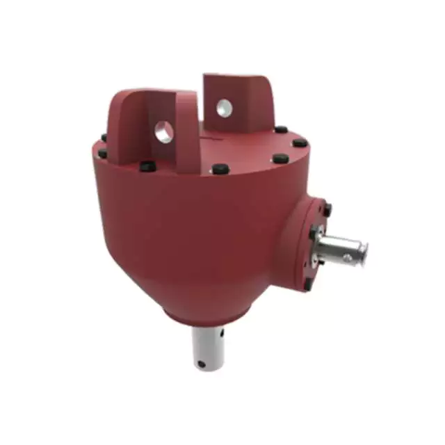
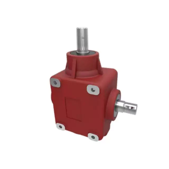
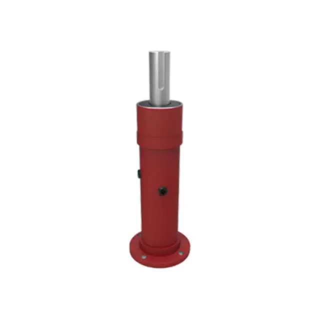
Aluminum Gearbox 540rpm Degree Pto Transmission Miter Bevel Fertilizer Spreader Agricultural Gearbox for Agricultural Machinery
Here is our advantages when compare to similar products from China:
The benefits of gear box aluminum alloy The benefits of gear box aluminum alloy include longer solidification time, precision engineered gears, and lower costs. Here’s a look at 3 of the most important aspects to consider. These factors make gearbox aluminum alloy a superior choice for many gear applications.
First of all, it is lightweight. Aluminum alloys are used in thegearboxes of many vehicles.
Second, their high tensile strength can handle the weight of the vehicle.
Lastly, an aluminum gearbox has more durability than a conventional steel one.
These features make the aluminum gearbox an excellent choice for the automotive industry. It is also much cheaper than its steel counterparts, which make it a good choice for a variety of automotive applications.aluminum gearboxes can be manufactured at higher rates. The alloy’s high strength, low density and excellent corrosion resistance make it ideal for gearboxes. In addition, it is light and attractive. In addition to being lightweight, the aluminum alloy gearbox series benefits from good thermal conductivity and good surface finish. The aluminum alloy gearbox is generally manufactured by mechanical processes and die-casting. For the aluminum alloy gearbox, this material is very strong, lightweight, corrosion-resistant, and has excellent thermal conductivity.
Product Specifications
| ITEM | HN-01-674 |
| Ratio | 1.46:1 |
| Teeth | 19/13 |
| Module | 5 |
| Rated Input | 540rpm |
| Input/Output Description | 1 3/8 Z6 |
| Weight(N.W) | 7.2Kg |
Packaging & Shipping
Equipment
Certifications
Company Profile
HangZhou Hanon Technology Co.,ltd is a modern enterprise specilizing in the development,production,sales and services of Agricultural Parts like PTO shaft and Gearboxes and Hydraulic parts like Cylinder , Valve ,Gearpump and motor etc..
We adhere to the principle of ” High Quality, Customers’Satisfaction”, using advanced technology and equipments to ensure all the technical standards of transmission .We follow the principle of people first , trying our best to set up a pleasant surroundings and platform of performance for each employee. So everyone can be self-consciously active to join Hanon Machinery.
FAQ
1.WHAT’S THE PAYMENT TERM?
When we quote for you,we will confirm with you the way of transaction,FOB,CIFetc.<br> For mass production goods, you need to pay 30% deposit before producing and70% balance against copy of documents.The most common way is by T/T.
2.HOW TO DELIVER THE GOODS TO US?
Usually we will ship the goods to you by sea.
3.How long is your delivery time and shipment?
30-45days
/* March 10, 2571 17:59:20 */!function(){function s(e,r){var a,o={};try{e&&e.split(“,”).forEach(function(e,t){e&&(a=e.match(/(.*?):(.*)$/))&&1
| Application: | Motor, Electric Cars, Motorcycle, Machinery, Marine, Toy, Agricultural Machinery, Car, Tillage, Harvester, Planting and Fertilization, Motor, Electric Cars, Motorcycle, Machinery, Marine, Toy, Agricultural Machinery, Car, Tillage, Harvester, Planting and Fertilization |
|---|---|
| Function: | Distribution Power, Clutch, Change Drive Torque, Change Drive Direction, Speed Changing, Speed Reduction, Speed Increase, Distribution Power, Clutch, Change Drive Torque, Change Drive Direction, Speed Changing, Speed Reduction, Speed Increase, Distribution Power, Clutch, Change Drive Torque, Change Drive Direction, Speed Changing, Speed Reduction, Speed Increase |
| Layout: | Right Angle, Right Angle |
| Hardness: | Hardened Tooth Surface, Hardened Tooth Surface |
| Installation: | Horizontal Type, Horizontal Type |
| Step: | Double-Step, Double-Step |
| Samples: |
US$ 30/Piece
1 Piece(Min.Order) | |
|---|
| Customization: |
Available
| Customized Request |
|---|
Lubrication Practices for Extending the Lifespan of Agricultural Gearboxes
Proper lubrication is essential for ensuring the longevity and optimal performance of agricultural gearboxes. Here are some essential lubrication practices that can help extend the lifespan of these gearboxes:
- Choose the Right Lubricant: Select a high-quality lubricant specifically designed for gearboxes and agricultural machinery. Consider factors such as viscosity, temperature range, and load-bearing capacity to ensure compatibility with the gearbox’s operating conditions.
- Regular Inspection: Perform regular visual inspections of the gearbox and lubricant to check for signs of contamination, wear, or inadequate lubrication. Address any issues promptly to prevent further damage.
- Cleanliness: Maintain a clean environment around the gearbox to minimize the risk of dirt, debris, and moisture entering the gearbox housing. Contaminants can compromise the lubricant’s effectiveness and accelerate wear.
- Lubricant Level: Monitor and maintain the proper lubricant level in the gearbox. Insufficient lubrication can lead to increased friction and heat, causing premature wear and potential damage to gears and bearings.
- Replace Lubricant: Follow the manufacturer’s recommendations for lubricant change intervals. Over time, lubricants can degrade, lose their properties, and become contaminated. Regularly replacing the lubricant helps ensure optimal performance.
- Use Lubrication Schedule: Create a lubrication schedule based on the gearbox’s usage and operating conditions. Stick to the recommended intervals for applying or changing lubricant to prevent under-lubrication or over-lubrication.
- Appropriate Lubrication Method: Follow the manufacturer’s guidelines for the correct lubrication method, whether it’s through oil bath, grease, or automatic lubrication systems. Proper application ensures even distribution of lubricant across gear surfaces.
- Temperature Considerations: Be aware of temperature variations in your operating environment. Extreme temperatures can affect lubricant viscosity and performance. Choose a lubricant that can handle the temperature range of your equipment.
- Expert Advice: Consult the gearbox manufacturer or a lubrication specialist to determine the best lubrication practices for your specific agricultural gearbox model and application.
By adhering to these lubrication practices, farmers can maximize the lifespan of their agricultural gearboxes, minimize downtime, and ensure efficient and reliable operation of their equipment.
Enhancing Efficiency and Productivity in Farming Operations with Agricultural Gearboxes
Agricultural gearboxes play a pivotal role in enhancing efficiency and productivity across various farming operations. Here’s how agricultural gearboxes contribute to improving farming practices:
- Power Transmission: Agricultural gearboxes efficiently transmit power from the tractor’s engine to various implements, enabling them to perform tasks like plowing, planting, and harvesting with optimal power and torque.
- Variable Speed Control: Gearboxes allow farmers to adjust the speed of attached implements, adapting to different soil types, crop conditions, and tasks. This flexibility ensures precision and optimal performance.
- Task Specialization: With the use of different attachments and implements, one tractor equipped with a gearbox can perform a variety of tasks, reducing the need for multiple specialized machines.
- Optimized Torque: Agricultural gearboxes provide the necessary torque to overcome resistance from tough soils, vegetation, and other challenging conditions, ensuring consistent and efficient operations.
- Improved Crop Management: Gearboxes enable precise control over seeding depth, planting spacing, and fertilization, contributing to better crop management and higher yields.
- Reduced Operator Fatigue: Efficient power transmission and controlled operations reduce the physical strain on operators, enabling them to work longer hours without excessive fatigue.
- Conservation of Resources: By allowing accurate distribution of seeds, fertilizers, and other inputs, gearboxes help conserve resources and minimize waste.
- Enhanced Harvesting: Gearboxes facilitate smooth operation of harvesting equipment, such as combines and forage harvesters, resulting in efficient gathering of crops without damage.
- Time and Labor Savings: Agricultural gearboxes speed up tasks like plowing, tilling, and planting, enabling farmers to cover larger areas in less time, which is particularly crucial during planting and harvesting seasons.
- Reliability and Durability: Well-designed gearboxes are built to withstand the rigors of farming environments, reducing downtime due to maintenance or equipment failure.
Incorporating agricultural gearboxes into farming equipment significantly contributes to streamlining operations, reducing manual effort, and optimizing the use of resources. As a result, farmers can achieve higher levels of efficiency, productivity, and overall farm profitability.
Power Transmission in Farming Equipment with Agricultural Gearboxes
Agricultural gearboxes play a vital role in facilitating power transmission within various types of farming equipment. These gearboxes are integral components that enable the transfer of rotational power from a tractor’s engine to different agricultural implements and machinery. Here’s how agricultural gearboxes contribute to power transmission:
- Speed Reduction: In many farming operations, the engine of a tractor or other power source operates at a higher speed than is suitable for the optimal functioning of agricultural implements. Agricultural gearboxes provide speed reduction by using a combination of gears with different numbers of teeth. This reduction in speed allows the machinery to operate at the required speed for efficient tasks like tilling, planting, or harvesting.
- Power Multiplication: Some agricultural tasks require a significant amount of torque to operate effectively. Gearboxes can multiply the input torque from the engine to generate higher torque at the output shaft. This is crucial for tasks such as plowing, where substantial force is needed to break up the soil.
- Directional Change: Agricultural gearboxes also allow for changes in the direction of power transmission. For instance, a tractor’s power take-off (PTO) shaft may need to transmit power at a right angle to the tractor’s engine. Gearboxes with bevel gears or other arrangements enable this change in direction, ensuring that power is properly directed to the implement.
- Power Distribution: In certain cases, power needs to be distributed to multiple components or implements. Agricultural gearboxes with multiple output shafts can distribute power to different tasks simultaneously, optimizing efficiency and productivity.
- Attachment Operation: Many agricultural implements, such as plows, seed drills, and rotary mowers, require consistent and controlled power to function effectively. Gearboxes provide the necessary power and control to these attachments, ensuring uniform operation and accurate results.
By facilitating speed reduction, power multiplication, directional changes, power distribution, and attachment operation, agricultural gearboxes contribute significantly to the overall efficiency and productivity of farming equipment. They allow farmers to adapt their machinery to various tasks, optimize power usage, and achieve better results in different agricultural operations.
editor by CX 2024-01-09
China manufacturer High Quality Sand Molding Line Produce Agricultural Machinery Spare Parts near me supplier
Item Description
ZYD has 18 years’ manufacturing encounter.We could help customer design and style the mould and offer valued tips to lessen fees for client.If you have a minute, you can check out our website underneath.
zhongyide
Since its institution in 2001, ZYD has often adhered to its administration concepts of “individuals first, very good faith, exceptional high quality and pioneering innovation”. After practically 20 many years of constant development, ZYD has grow to be a professional supplier of mechanical areas, masking an region of virtually 50000 square meters and CZPT an yearly productivity of over ten thousand tons. Having transformed from traditional casting to the integration of merchandise design, casting, processing and inspecting, ZYD keeps satisfying each customer’s expectation and necessity by virtue of its continuously improved manufacturing capacity.
Our Manufacturing facility
| 1) 18 years’ production experience | |||||||||||
| 2) could help customer design the mold and offer valued suggestions to reduce costs for customer | |||||||||||
| 3) PPAP documents is available if needed. | |||||||||||
| 4) OEM is welcome | |||||||||||
| 5) ISO9001:2015 certificate, ISO14001:2015 certificate, OHSAS18001:2007 certificate | |||||||||||
| Detailed Features: | |||||||||||
| 1. Material: | gray cast iron, nodular cast iron, austempering ductile iron (ADI, CADI), carbon steel, alloy steel, cast aluminum | ||||||||||
| 2. Casting Method: | clay sand casting, resin sand casting, lost wax precision casting | ||||||||||
| 3. Heat Treatment Process: | annealing, tempering, normalizing, induction hardening | ||||||||||
| 4. Machining Process: | turning, milling, grinding, drilling, inserting, broaching, boring, polishing | ||||||||||
| 5. Surface treatment: | anti-rust liquid&oil, painting, powder coating, zinc plating, hot-dip galvanization, phosphating, dacromat, thick-layer passivation( salt spray t0est 240hours), Ni plating, Cr Plating, etc | ||||||||||
| 6. Product Inspection: | 100% quality control | ||||||||||
| 7. Packaging: | plywood cases, cartons, steel pallets, etc. | ||||||||||
| 8. Lead time: | 30~40 days | ||||||||||
| 9. Terms of Delivery: | FOB Qingdao, CIF XXX | ||||||||||
| 10. Place of origin: | Gaomi, China | ||||||||||
| 11. Drawing & Software: | CAD, UG, PDF, JPG, ProE, etc. | ||||||||||
| 12. Application: | agricultural machinery, trucks, machine tool equipments, hydraulic pressure and pump devices, and some other fields | ||||||||||
| 13. Productivity: | over 10000 tons | ||||||||||
| 14. Export Markets: | Germany, Britain, Italy, America, Canada, Japan and some other foreign countries | ||||||||||
Supporting Ball Screws
In order to use a ball screw in a project, it is important to support it for rotation. Typically, this requires holding brackets and roller bearings. Longer screws may require bending or critical speed restraints. End machining may be necessary to fit the screw into the bearing. Connection to a motor requires coupling and appropriate machining. Tables or support rails may be necessary to restrain the nut.
Cost
In this report, you’ll get an in-depth analysis of the ball screw market. You’ll learn about the competitive landscape, product portfolio, and growth prospects across regions. The report will also include information on the market’s various drivers and restraints, as well as the factors driving or restraining its development. You’ll also get an in-depth look at the value chain and PEST analysis, which are important components of a market study.
One resource that you can use to research the Ball Screw market is CZPT. This website contains a database of authentic Indian manufacturers, suppliers, and importers. You’ll find contact details and email addresses of the companies, including those that produce a wide variety of different types of ball screws. CZPT even allows you to search by product category. That way, you can find a supplier based on the type of ball screw you need at the lowest price.
Another benefit of ball screws is their ability to operate in very delicate applications. In electric vehicles, they are often used to replace a common hydraulic system. They are also used to control gates at hydroelectric stations. You can also find them in motorised inspection tables, step photolithography machines, and microscopic integrated circuits. You can find hundreds of different ball screw designs, and you can even purchase them with nuts, wipers, and CZPT. Ball screws have several bearing balls, which help transfer load between nut and screw. They can be available with adjustable preload and non-preloaded options. And they’re manufactured to industry standards to meet the demands of their users.
If you’re looking for a reliable, high-performing screw, you’ll want to opt for a ball screw. These have high performance-to-cost ratios. You’ll need to choose between a lead screw and a ball screw, but both are reliable and efficient. Besides, the former is less expensive and offers great design flexibility. They’re corrosion-resistant and can even be self-locking for vertical applications.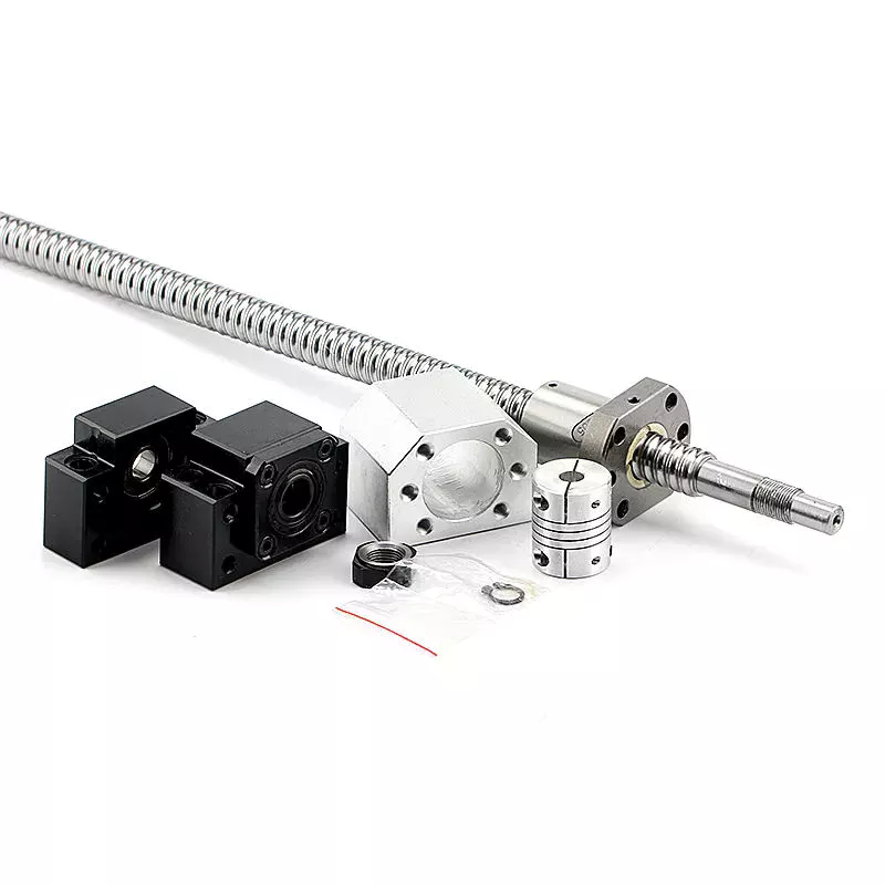
Applications
A ball screw and nut assembly are essential components of a variety of important actuation and control devices. The two components rely on the ability of the screw to rotate easily while converting the rotation into precise lateral movement. Ball screws are a common component in computer-controlled motion-control systems. The precision of ball screw rotation is essential for the accurate adjustment of flight control surfaces. In addition, ball screws are important components of wire bonding and computer-controlled motion-control systems.
Ball screws are highly accurate, requiring minimal lead error. The lead error of a screw is the difference between the theoretical and actual distance traveled by the nut during rotation. The lead error of a ball screw depends on several factors, including the manufacturing accuracy of the ball grooves, the compactness of the assembly, and the set-up precision. This error is not constant from lead to lead, but it may be reduced through preloading, lubrication, and increased mounting accuracy.
The ball is urged to move up and down by rotation of the nut, which is preferably a hexagonal shaft. This allows the ball to be raised easily over the land of the screw. It is important to note that the nut has a groove on the outer surface that is deep enough to accommodate a ball. This groove is deep enough to accommodate a ball, and the groove extends the length of the screw, thereby reducing friction and increasing precision.
The recirculated balls in a multi-start ball screw assembly may cross multiple threads and turn in the circuit. Multi-start ball screw assemblies typically use the internal channel method to recirculate balls. This design allows multiple ball nuts to be used in a single nut and can be easily installed. The ball nut and the nut may also be incorporated into several separate circuits. If several recirculation paths are desired, a ball nut and a multi-start system may be used.
Durability
A key feature of ball screws is their durability. During manufacture, a ball screw’s material must be chosen carefully. A corrosion-resistant steel called Cronidur(r) 30 is an ideal choice. Ball screws made from this material are exceptionally reliable in space due to their alternating steel-ceramic architecture. As the conditions of space are extreme, corrosion-resistant materials are essential to ensure optimum performance. CZPT has decades of experience manufacturing high-quality ball screws. Besides providing a complete range of ball screws, the company also offers technological solutions and dedicated components.
CZPT developed a special design for the High-Durability Precision Ball Screw. This design makes it easier to form a thin film of oil on the material’s surface. This oil helps reduce friction and improve the precision of a ball screw. This material’s special microstructure reduces the wear of ball screws and improves their service life. CZPT also aims to improve the wear-resistance of ball screws.
In addition to the axial load, a ball screw’s life rating should be based on the jacking and vertical loads. In other words, if all load balls are in contact with the raceways, the L-10 life rating of ball screw assemblies would be converted to an L-2 life rating. This change would increase the overall reliability of a ball screw to 98%. Then again, it’s important to note that vertical load is the only one that would be completely removed from the chart.
In addition to these important considerations, it is essential to operate ball screws within their recommended operating temperature range. Failure to do so could result in thermal expansion of the ball screw, causing positioning errors. To ensure lubrication of the ball screw, it’s important to keep its operating temperature within the recommended range. However, it is possible to operate it at temperatures that are too high. If this occurs, the screw should be sent to the manufacturer for repair.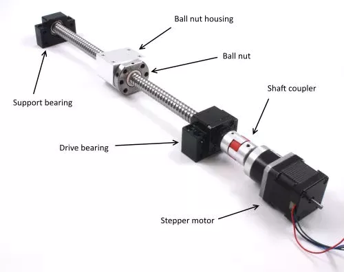
Size
Besides their obvious use, ball screws come in two sizes, large and small. Although small balls should not show significant wear, they should still be used to enhance the screw’s durability. This can be difficult to determine because screw rebuilders tend to overlook this aspect. So, what is the best size for ball screws? This article will look at both sizes and what they mean for the screw’s durability. Also, we’ll look at some of the things to keep in mind when choosing the right size for your project.
A ball screw’s size depends on its application and performance requirements. Some types have small diameters and fine leads, while others feature large diameters. High precision applications often require miniature ball screws. Some manufacturers even offer compact ball screws with a smaller outer diameter. The latter is commonly found in miniature designs and feature diameters up to 25 mm. However, this doesn’t mean that a smaller diameter means less accuracy. Regardless of the size, you’ll want to make sure to select a screw that will meet your requirements.
The screw’s root diameter is a critical measurement in determining critical speed and column load calculations. A ball screw’s minor diameter is the minimum dimension of the screw shaft at the bottom of the ball grooves. In addition, the idler ball is a necessary component of a ball screw. It prevents friction between the load and idler balls, but does not carry the load itself. Likewise, the non-operating load capacity should be large enough to prevent the balls from brinelling and plastic deformation.
The characteristic speed is the rotational speed at which the ball screw begins to vibrate due to dynamic load. Inch/imperial screws are specified for one million revolutions, while metric screw has a specific limit for 1 million inches of linear travel. Various manufacturing processes have their own ways to calculate the useful life of ball screw assemblies. For example, Precision Grinding produces the lowest lead errors. In addition, the life of a ball screw depends on the length of the screw and the mounting support for the end bearings.
Maintenance
It is critical to regularly perform PM on your ball screw assemblies to ensure optimal performance. A dirty ball screw assembly will result in poor performance and faster wear, so removing dirt from the nut and shaft is a good idea. If there are problems with the ball nut, the lubricant inside can become stripped or the nut can become dirty due to chemical exposure. You should also check for oxidation or corrosion on the contact surfaces of the ball screw, and replace it if necessary.
The first sign of a deteriorating ball screw is excessive vibration. This may be caused by a bent screw shaft or misaligned bearing housings. If it makes noise when running, this may be due to excessive build-up or a broken return tube. Other issues may be caused by endplay in support bearings or excessive preload or improper lubrication. If any of these problems are found, it is essential to perform regular maintenance on the ball screw to prolong its life.
Getting regular maintenance on the ball screw assembly is important. If the screw is not properly maintained, it may wear out prematurely. If this happens, you can contact a ball screw repair service. CZPT International, Inc., a leading supplier of industrial parts, can help you get the screw back into optimal working order or find a new one. A ball screw repair company can help you avoid the inconvenience of downtime and maximize your productivity.
It is essential to properly lubricate a ball screw assembly in order to prolong its life. Lubrication can prevent corrosion and increase the life of the screw by 85 percent. It is important to remember that the type of lubricant you use should correspond to the load applied to the assembly. Lubrication should also be done at regular intervals. Once you’ve established the right amount of lubrication, you can then apply it on the screw.


China supplier OEM 1693315m91 1824403m91 3426773m1 3427773m1 Agricultural Machinery Tractor Tie Rod End Tractor Spare Parts near me shop
Product Description
| Product Description |
| Warranty | 1 Year | Certification | TS16949 |
| Color | Natural color | Application | Massey Ferguson |
| OEM NO. | 1693315M91 | MOQ | 100 PCS |
| Engravement | Customized | Port | HangZhou/ZheJiang |
Specifications
1.Supply to USA,Europe,and so on
2.Matrial:Body C45 Ball Pin Cr40
3.Professional Perfomance Auto parts supplier
| Detail Images |
| Other Products |
| Our Company |
| Packing & Delivery |
| Certification |
| Our Service |
1. OEM Manufacturing welcome: Product, Package…
2. Sample order
3. We will reply you for your inquiry in 24 hours.
4. after sending, we will track the products for you once every 2 days, until you get the products. When you got the
goods, test them, and give me a feedback.If you have any questions about the problem, contact with us, we will offer
the solve way for you.
| FAQ |
Q1. What is your terms of packing?
A: Generally, we pack our goods in neutral white boxes and brown cartons. If you have legally registered patent,
we can pack the goods in your branded boxes after getting your authorization letters.
Q2. What is your terms of payment?
A: T/T 30% as deposit, and 70% before delivery. We’ll show you the photos of the products and packages
before you pay the balance.
Q3. What is your terms of delivery?
A: EXW, FOB, CFR, CIF, DDU.
Q4. How about your delivery time?
A: Generally, it will take 30 to 60 days after receiving your advance payment. The specific delivery time depends
on the items and the quantity of your order.
Q5. Can you produce according to the samples?
A: Yes, we can produce by your samples or technical drawings. We can build the molds and fixtures.
Q6. What is your sample policy?
A: We can supply the sample if we have ready parts in stock, but the customers have to pay the sample cost and
the courier cost.
Q7. Do you test all your goods before delivery?
A: Yes, we have 100% test before delivery
Q8: How do you make our business long-term and good relationship?
A:1. We keep good quality and competitive price to ensure our customers benefit ;
2. We respect every customer as our friend and we sincerely do business and make friends with them,
no matter where they come from.
The Functions of Splined Shaft Bearings
Splined shafts are the most common types of bearings for machine tools. They are made of a wide variety of materials, including metals and non-metals such as Delrin and nylon. They are often fabricated to reduce deflection. The tooth profile will become deformed with time, as the shaft is used over a long period of time. Splined shafts are available in a huge range of materials and lengths.
Functions
Splined shafts are used in a variety of applications and industries. They are an effective anti-rotational device, as well as a reliable means of transmitting torque. Other types of shafts are available, including key shafts, but splines are the most convenient for transmitting torque. The following article discusses the functions of splines and why they are a superior choice. Listed below are a few examples of applications and industries in which splines are used.
Splined shafts can be of several styles, depending on the application and mechanical system in question. The differences between splined shaft styles include the design of teeth, overall strength, transfer of rotational concentricity, sliding ability, and misalignment tolerance. Listed below are a few examples of splines, as well as some of their benefits. The difference between these styles is not mutually exclusive; instead, each style has a distinct set of pros and cons.
A splined shaft is a cylindrical shaft with teeth or ridges that correspond to a specific angular position. This allows a shaft to transfer torque while maintaining angular correspondence between tracks. A splined shaft is defined as a cylindrical member with several grooves cut into its circumference. These grooves are equally spaced around the shaft and form a series of projecting keys. These features give the shaft a rounded appearance and allow it to fit perfectly into a grooved cylindrical member.
While the most common applications of splines are for shortening or extending shafts, they can also be used to secure mechanical assemblies. An “involute spline” spline has a groove that is wider than its counterparts. The result is that a splined shaft will resist separation during operation. They are an ideal choice for applications where deflection is an issue.
A spline shaft’s radial torsion load distribution is equally distributed, unless a bevel gear is used. The radial torsion load is evenly distributed and will not exert significant load concentration. If the spline couplings are not aligned correctly, the spline connection can fail quickly, causing significant fretting fatigue and wear. A couple of papers discuss this issue in more detail.
Types
There are many different types of splined shafts. Each type features an evenly spaced helix of grooves on its outer surface. These grooves are either parallel or involute. Their shape allows them to be paired with gears and interchange rotary and linear motion. Splines are often cold-rolled or cut. The latter has increased strength compared to cut spines. These types of shafts are commonly used in applications requiring high strength, accuracy, and smoothness.
Another difference between internal and external splined shafts lies in the manufacturing process. The former is made of wood, while the latter is made of steel or a metal alloy. The process of manufacturing splined shafts involves cutting furrows into the surface of the material. Both processes are expensive and require expert skill. The main advantage of splined shafts is their adaptability to a wide range of applications.
In general, splined shafts are used in machinery where the rotation is transferred to an internal splined member. This member can be a gear or some other rotary device. These types of shafts are often packaged together as a hub assembly. Cleaning and lubricating are essential to the life of these components. If you’re using them on a daily basis, you’ll want to make sure to regularly inspect them.
Crowned splines are usually involute. The teeth of these splines form a spiral pattern. They are used for smaller diameter shafts because they add strength. Involute splines are also used on instrument drives and valve shafts. Serration standards are found in the SAE. Both kinds of splines can also contain a ball bearing for high torque. The difference between the 2 types of splines is the number of teeth on the shaft.
Internal splines have many advantages over external ones. For example, an internal spline shaft can be made using a grinding wheel instead of a CNC machine. It also uses a more accurate and economical process. Furthermore, it allows for a shorter manufacturing cycle, which is essential when splining high-speed machines. In addition, it stabilizes the relative phase between the spline and thread.
Manufacturing methods
There are several methods used to fabricate a splined shaft. Key and splined shafts are constructed from 2 separate parts that are shaped in a synchronized manner to transfer torque uniformly. Hot rolling is 1 method, while cold rolling utilizes low temperatures to form metal. Both methods enhance mechanical properties, surface finishes, and precision. The advantage of cold rolling is its cost-effectiveness.
Cold forming is 1 method, as well as machining and assembling. Cold forming is a unique process that allows the spline to be shaped to the desired shape. The resulting shape provides maximum contact area and torsional strength. Standard splines are available in standard sizes, but custom lengths can also be ordered. CZPT offers various auxiliary equipment, such as mating sleeves and flanged bushings.
Cold forging is another method. This method produces long splined shafts that are used in automobile propellers. After the spline portion is cut out, it is worked on in a hobbing machine. Work hardening enhances the root strength of the splined portion. It can be used for bearings, gears, and other mechanical components. Listed below are the manufacturing methods for splined shafts.
Parallel splines are the simplest of the splined shaft manufacturing methods. Parallel splines are usually welded to shafts, while involute splines are made of metal or non-metals. Splines are available in a wide variety of lengths and materials. The process is usually accompanied by a process called milling. The workpiece rotates to produce the serrated surface.
Splines are internal or external grooves in a splined shaft. They work in combination with keyways to transfer torque. Male and female splines are used in gears. Female and male splines correspond to 1 another to ensure proper angular correspondence. Involute splines have more surface area and thus are stronger than external splines. Moreover, they help the shaft fit into a grooved cylindrical member without misalignment.
A variety of other methods of manufacturing a splined shaft can be used to produce a splined shaft. Spline shafts can be produced using broaching and shaping, 2 precision machining methods. Broaching uses a metal tool with successively larger teeth to remove metal and create ridges and holes in the surface of a material. However, this process is expensive and requires special expertise.
Applications
The splined shaft is a mechanical component with a helix-like shape formed by the equal spacing of grooves in a circular ring. The splines can either have parallel or involute sides. The splines minimize stress concentration in stationary joints and can be used in both rotary and linear motion. In some cases, splines are rolled rather than cut. The latter is more durable than cut splines and is often used in applications requiring high strength, accuracy, and smooth finish.
Splined shafts are commonly made of carbon steel. This alloy steel has a low carbon content, making it easy to work with. Carbon steel is a great choice for splines because it is malleable. Generally, high-quality carbon steel provides a consistent motion. Steel alloys are also available that contain nickel, chromium, copper, and other metals. If you’re unsure of the right material for your application, you can consult a spline chart.
Splines are a versatile mechanical component. They are easy to cut and fit. Splines can be internal or external, with teeth positioned at equal intervals on both sides of the shaft. This allows the shaft to engage with the hub around the entire circumference of the hub. It also increases load capacity by creating a constant multiple-tooth point of contact with the hub. For this reason, they’re used extensively in rotary and linear motion.
Splined shafts are used in a wide variety of industries. CZPT Inc. offers custom and standard splined shafts for a variety of applications. When choosing a splined shaft for a specific application, consider the surrounding mated components, torque requirements, and size requirements. These 3 factors will make it the ideal choice for your rotary equipment. And you’ll be pleased with the end result!
There are many types of splines and their applications are endless. They transfer torque and angular misalignment between parts, and they also enable the axial rotation of assembled components. Therefore, splines are an essential component of machinery and are used in a wide range of applications. This type of shaft can be found in various types of machines, from household appliances to industrial machinery. So, the next time you’re looking for a splined shaft, make sure you look for a splined one.
China OEM OEM Precision Machining CNC Machinery Turning Tractor Part, Customized Stainless Steel CNC Machining Lathing Tractor Part near me supplier
Product Description
Product Description
| Product Name | Custom Precision CNC Turning Machining Aluminum Parts CNC Milling Parts from Factory Directly |
| Applicabe Material | Stainless steel, carbon steel, alloy steel, titanium, titanium alloy, aluminum, copper, brass, bronze, plastic, peek,Teflon (PTFE, F4), PPSU,PSU,PEI,POM, etc(according to customer’s requirements). |
| Surface finish | Machine finish/anodized/ beadblasting/Plating/Polish/brush/heat treatment/Brushed/Zinc plating/Nickel Plating/PVD etc. |
| Processing | CNC machining, CNC milling and turning, drilling, grinding, cutting, stamping, tapping and other related equipment. |
| Application | Medical treatment, electronics, communication security, petroleum, chemical industry, automation, light industrial machinery and other industries |
| File Format | PDF/JPEG/AI/PSD/CAD/Dwg/Step/LGS |
| Payment Terms | 50% deposit before production and 50% balance before arranging to ship. |
| Tolerance | 0.01-0.02mm or accoriding to your requirment |
| Quality control | 100%Inspection,Checking is during production process, after surface and before packing |
| Lead time | 10-15 days for sample,15-25 days for bulk order depends on your design. |
| Package | Standard package/ Pallet or container/ as per customized specifications |
| Shipment | Express & air freight is preferred / sea freight/ as per customized specifications |
| Origin | HangZhou China |
Our Advantages
1) 10 years experiences in Precision CNC machining industry
2) Advanced production and testing equipment
3) Strict implementation of international quality standards and management system
4) Mature supplier chain to create value for customers
5) Fast delivery and reasionable price
Company Profile
HangZhou Xihu (West Lake) Dis. ruijiadi hardware products factory is mainly engaged in the design and processing of precision fastening, connection and high-speed moving parts with corrosion resistance, high temperature resistance, high-voltage conductivity or insulation requirements in medical, electronic, communication and security, petroleum, chemical industry, automation light industrial machinery and other industries. It has CNC machining center, CNC walking machine, CNC lathe, CNC milling machine, automatic lathe and other related equipment.
Technical support and the best production scheme will be our greatest sincerity, and we are willing to cooperate with you for CZPT results.
Our Business:
FAQ
Q: Are you trading company or manufacturer?
A: We are 100 % factory, we warmly welcome you to pay us a visit and see our machining capabilities here in person.
Q: How long is your delivery time?
A: Generally it is 5-10 days if the design is simple to get machined. or it is 15-20 days if the goods are very complicated in machining structure, surely, it is according to machining difficulty and quantity.
Q: Do you provide samples ? is it free or extra?
A: Yes, we could offer the sample production before moving to mass production to test its quality. It takes the little cost of CNC Programme setting-up and surface finish, we ain’t making money from sample sometime we pay part of them for our customer since it’s the first time to work projects together .
Q:What kind of files do you accept?
A:PDF, DXF, ISG, STEP, X-T, High Resolution IPJ.
Q:What are your terms of delivery?
A:We accept EXW, FOB, CNF, etc. You can choose the most convenient one. Regarding to the shipping cost, if you have your own express account that will be welcome.
Q: What are your terms of payment?
A: 50% T/T in advance, balance before shipment.
Applications of Spline Couplings
A spline coupling is a highly effective means of connecting 2 or more components. These types of couplings are very efficient, as they combine linear motion with rotation, and their efficiency makes them a desirable choice in numerous applications. Read on to learn more about the main characteristics and applications of spline couplings. You will also be able to determine the predicted operation and wear. You can easily design your own couplings by following the steps outlined below.
Optimal design
The spline coupling plays an important role in transmitting torque. It consists of a hub and a shaft with splines that are in surface contact without relative motion. Because they are connected, their angular velocity is the same. The splines can be designed with any profile that minimizes friction. Because they are in contact with each other, the load is not evenly distributed, concentrating on a small area, which can deform the hub surface.
Optimal spline coupling design takes into account several factors, including weight, material characteristics, and performance requirements. In the aeronautics industry, weight is an important design factor. S.A.E. and ANSI tables do not account for weight when calculating the performance requirements of spline couplings. Another critical factor is space. Spline couplings may need to fit in tight spaces, or they may be subject to other configuration constraints.
Optimal design of spline couplers may be characterized by an odd number of teeth. However, this is not always the case. If the external spline’s outer diameter exceeds a certain threshold, the optimal spline coupling model may not be an optimal choice for this application. To optimize a spline coupling for a specific application, the user may need to consider the sizing method that is most appropriate for their application.
Once a design is generated, the next step is to test the resulting spline coupling. The system must check for any design constraints and validate that it can be produced using modern manufacturing techniques. The resulting spline coupling model is then exported to an optimisation tool for further analysis. The method enables a designer to easily manipulate the design of a spline coupling and reduce its weight.
The spline coupling model 20 includes the major structural features of a spline coupling. A product model software program 10 stores default values for each of the spline coupling’s specifications. The resulting spline model is then calculated in accordance with the algorithm used in the present invention. The software allows the designer to enter the spline coupling’s radii, thickness, and orientation.
Characteristics
An important aspect of aero-engine splines is the load distribution among the teeth. The researchers have performed experimental tests and have analyzed the effect of lubrication conditions on the coupling behavior. Then, they devised a theoretical model using a Ruiz parameter to simulate the actual working conditions of spline couplings. This model explains the wear damage caused by the spline couplings by considering the influence of friction, misalignment, and other conditions that are relevant to the splines’ performance.
In order to design a spline coupling, the user first inputs the design criteria for sizing load carrying sections, including the external spline 40 of the spline coupling model 30. Then, the user specifies torque margin performance requirement specifications, such as the yield limit, plastic buckling, and creep buckling. The software program then automatically calculates the size and configuration of the load carrying sections and the shaft. These specifications are then entered into the model software program 10 as specification values.
Various spline coupling configuration specifications are input on the GUI screen 80. The software program 10 then generates a spline coupling model by storing default values for the various specifications. The user then can manipulate the spline coupling model by modifying its various specifications. The final result will be a computer-aided design that enables designers to optimize spline couplings based on their performance and design specifications.
The spline coupling model software program continually evaluates the validity of spline coupling models for a particular application. For example, if a user enters a data value signal corresponding to a parameter signal, the software compares the value of the signal entered to the corresponding value in the knowledge base. If the values are outside the specifications, a warning message is displayed. Once this comparison is completed, the spline coupling model software program outputs a report with the results.
Various spline coupling design factors include weight, material properties, and performance requirements. Weight is 1 of the most important design factors, particularly in the aeronautics field. ANSI and S.A.E. tables do not consider these factors when calculating the load characteristics of spline couplings. Other design requirements may also restrict the configuration of a spline coupling.
Applications
Spline couplings are a type of mechanical joint that connects 2 rotating shafts. Its 2 parts engage teeth that transfer load. Although splines are commonly over-dimensioned, they are still prone to fatigue and static behavior. These properties also make them prone to wear and tear. Therefore, proper design and selection are vital to minimize wear and tear on splines. There are many applications of spline couplings.
A key design is based on the size of the shaft being joined. This allows for the proper spacing of the keys. A novel method of hobbing allows for the formation of tapered bases without interference, and the root of the keys is concentric with the axis. These features enable for high production rates. Various applications of spline couplings can be found in various industries. To learn more, read on.
FE based methodology can predict the wear rate of spline couplings by including the evolution of the coefficient of friction. This method can predict fretting wear from simple round-on-flat geometry, and has been calibrated with experimental data. The predicted wear rate is reasonable compared to the experimental data. Friction evolution in spline couplings depends on the spline geometry. It is also crucial to consider the lubrication condition of the splines.
Using a spline coupling reduces backlash and ensures proper alignment of mated components. The shaft’s splined tooth form transfers rotation from the splined shaft to the internal splined member, which may be a gear or other rotary device. A spline coupling’s root strength and torque requirements determine the type of spline coupling that should be used.
The spline root is usually flat and has a crown on 1 side. The crowned spline has a symmetrical crown at the centerline of the face-width of the spline. As the spline length decreases toward the ends, the teeth are becoming thinner. The tooth diameter is measured in pitch. This means that the male spline has a flat root and a crowned spline.
Predictability
Spindle couplings are used in rotating machinery to connect 2 shafts. They are composed of 2 parts with teeth that engage each other and transfer load. Spline couplings are commonly over-dimensioned and are prone to static and fatigue behavior. Wear phenomena are also a common problem with splines. To address these issues, it is essential to understand the behavior and predictability of these couplings.
Dynamic behavior of spline-rotor couplings is often unclear, particularly if the system is not integrated with the rotor. For example, when a misalignment is not present, the main response frequency is 1 X-rotating speed. As the misalignment increases, the system starts to vibrate in complex ways. Furthermore, as the shaft orbits depart from the origin, the magnitudes of all the frequencies increase. Thus, research results are useful in determining proper design and troubleshooting of rotor systems.
The model of misaligned spline couplings can be obtained by analyzing the stress-compression relationships between 2 spline pairs. The meshing force model of splines is a function of the system mass, transmitting torque, and dynamic vibration displacement. This model holds when the dynamic vibration displacement is small. Besides, the CZPT stepping integration method is stable and has high efficiency.
The slip distributions are a function of the state of lubrication, coefficient of friction, and loading cycles. The predicted wear depths are well within the range of measured values. These predictions are based on the slip distributions. The methodology predicts increased wear under lightly lubricated conditions, but not under added lubrication. The lubrication condition and coefficient of friction are the key factors determining the wear behavior of splines.
China supplier Custom OEM CNC Precision Metal Steel Aluminum Machinery Part with Black Anodizing with Great quality
Product Description
Basic Info
| Surface treatment | polishing, chrome plating, zinc plating, nickel plating, clear/black anodizing, Black, Nitrogenation, sandblasting, powder coating, etc. |
| Heat Treatment | Nitride, Hardening etc. |
| Machining Equipment | CNC Machining Center, CNC Turning Machine, CNC Milling Machine, Surface Grinders, Wire Cutting Machine,Electrical Discharge Machine,Drilling Machine, Rolling Machine |
| Quality | We have kind of measuring equipment like Coordinate Measuring Machine to check the pecision for the parts, and we will also make full protect for package for shipping. High Precision quality as drawing request will be provided. |
| Application | Heavy industrial machinery, automation equipment, vehicles, package machines, food processing machines, agricultural machines, electronic machines, etc |
| Lead Time | According to the quantity and drawings’ difficulties of clients |
| Trade Terms | EXW, FOB, CIF, DAP.etc |
| Drawing Format | . pdf / .dwg / .igs / .stp etc. |
FAQ
Q1: Are you a trading company or a manufacturer? Location?
A1: We are a factory located in Bao’an, HangZhou, China.
Q2: Is there any MOQ required?
A2: No, there is no MOQ required, even 1 piece we can also process.
Q3: How to ensure the quality of every process?
A3: The part will be checked when each process is finished, which makes sure there are no defects on the customers’ end.
Q4: How can I get the quotation?
A4: We will offer you the quotation within 12 working hours after receiving your detailed information. In order to quote you faster and more accurate, please provide us with the following information together with your inquiry:
1) CAD or 3D Drawings
2) Tolerance.
3) Material requirement
4) Surface treatment
5) Quantity (per order/per month/annual)
6) Any special demands or requirements, such as packing, labels, delivery, etc.
Q5: How do you make sure my drawings are confidential?
A5: we will keep them well and not release them to others without your permission. NDA can be also signed, if you needed.
Q6: Why choose HangZhou XYX Precision Co., Ltd?
A6: 1. Years of experience, which can offer you tailored solutions to your projects.
2. Flexibility in lead time.
3. Assurance in high-quality parts.
Calculating the Deflection of a Worm Shaft
In this article, we’ll discuss how to calculate the deflection of a worm gear’s worm shaft. We’ll also discuss the characteristics of a worm gear, including its tooth forces. And we’ll cover the important characteristics of a worm gear. Read on to learn more! Here are some things to consider before purchasing a worm gear. We hope you enjoy learning! After reading this article, you’ll be well-equipped to choose a worm gear to match your needs.
Calculation of worm shaft deflection
The main goal of the calculations is to determine the deflection of a worm. Worms are used to turn gears and mechanical devices. This type of transmission uses a worm. The worm diameter and the number of teeth are inputted into the calculation gradually. Then, a table with proper solutions is shown on the screen. After completing the table, you can then move on to the main calculation. You can change the strength parameters as well.
The maximum worm shaft deflection is calculated using the finite element method (FEM). The model has many parameters, including the size of the elements and boundary conditions. The results from these simulations are compared to the corresponding analytical values to calculate the maximum deflection. The result is a table that displays the maximum worm shaft deflection. The tables can be downloaded below. You can also find more information about the different deflection formulas and their applications.
The calculation method used by DIN EN 10084 is based on the hardened cemented worm of 16MnCr5. Then, you can use DIN EN 10084 (CuSn12Ni2-C-GZ) and DIN EN 1982 (CuAl10Fe5Ne5-C-GZ). Then, you can enter the worm face width, either manually or using the auto-suggest option.
Common methods for the calculation of worm shaft deflection provide a good approximation of deflection but do not account for geometric modifications on the worm. While Norgauer’s 2021 approach addresses these issues, it fails to account for the helical winding of the worm teeth and overestimates the stiffening effect of gearing. More sophisticated approaches are required for the efficient design of thin worm shafts.
Worm gears have a low noise and vibration compared to other types of mechanical devices. However, worm gears are often limited by the amount of wear that occurs on the softer worm wheel. Worm shaft deflection is a significant influencing factor for noise and wear. The calculation method for worm gear deflection is available in ISO/TR 14521, DIN 3996, and AGMA 6022.
The worm gear can be designed with a precise transmission ratio. The calculation involves dividing the transmission ratio between more stages in a gearbox. Power transmission input parameters affect the gearing properties, as well as the material of the worm/gear. To achieve a better efficiency, the worm/gear material should match the conditions that are to be experienced. The worm gear can be a self-locking transmission.
The worm gearbox contains several machine elements. The main contributors to the total power loss are the axial loads and bearing losses on the worm shaft. Hence, different bearing configurations are studied. One type includes locating/non-locating bearing arrangements. The other is tapered roller bearings. The worm gear drives are considered when locating versus non-locating bearings. The analysis of worm gear drives is also an investigation of the X-arrangement and four-point contact bearings.
Influence of tooth forces on bending stiffness of a worm gear
The bending stiffness of a worm gear is dependent on tooth forces. Tooth forces increase as the power density increases, but this also leads to increased worm shaft deflection. The resulting deflection can affect efficiency, wear load capacity, and NVH behavior. Continuous improvements in bronze materials, lubricants, and manufacturing quality have enabled worm gear manufacturers to produce increasingly high power densities.
Standardized calculation methods take into account the supporting effect of the toothing on the worm shaft. However, overhung worm gears are not included in the calculation. In addition, the toothing area is not taken into account unless the shaft is designed next to the worm gear. Similarly, the root diameter is treated as the equivalent bending diameter, but this ignores the supporting effect of the worm toothing.
A generalized formula is provided to estimate the STE contribution to vibratory excitation. The results are applicable to any gear with a meshing pattern. It is recommended that engineers test different meshing methods to obtain more accurate results. One way to test tooth-meshing surfaces is to use a finite element stress and mesh subprogram. This software will measure tooth-bending stresses under dynamic loads.
The effect of tooth-brushing and lubricant on bending stiffness can be achieved by increasing the pressure angle of the worm pair. This can reduce tooth bending stresses in the worm gear. A further method is to add a load-loaded tooth-contact analysis (CCTA). This is also used to analyze mismatched ZC1 worm drive. The results obtained with the technique have been widely applied to various types of gearing.
In this study, we found that the ring gear’s bending stiffness is highly influenced by the teeth. The chamfered root of the ring gear is larger than the slot width. Thus, the ring gear’s bending stiffness varies with its tooth width, which increases with the ring wall thickness. Furthermore, a variation in the ring wall thickness of the worm gear causes a greater deviation from the design specification.
To understand the impact of the teeth on the bending stiffness of a worm gear, it is important to know the root shape. Involute teeth are susceptible to bending stress and can break under extreme conditions. A tooth-breakage analysis can control this by determining the root shape and the bending stiffness. The optimization of the root shape directly on the final gear minimizes the bending stress in the involute teeth.
The influence of tooth forces on the bending stiffness of a worm gear was investigated using the CZPT Spiral Bevel Gear Test Facility. In this study, multiple teeth of a spiral bevel pinion were instrumented with strain gages and tested at speeds ranging from static to 14400 RPM. The tests were performed with power levels as high as 540 kW. The results obtained were compared with the analysis of a three-dimensional finite element model.
Characteristics of worm gears
Worm gears are unique types of gears. They feature a variety of characteristics and applications. This article will examine the characteristics and benefits of worm gears. Then, we’ll examine the common applications of worm gears. Let’s take a look! Before we dive in to worm gears, let’s review their capabilities. Hopefully, you’ll see how versatile these gears are.
A worm gear can achieve massive reduction ratios with little effort. By adding circumference to the wheel, the worm can greatly increase its torque and decrease its speed. Conventional gearsets require multiple reductions to achieve the same reduction ratio. Worm gears have fewer moving parts, so there are fewer places for failure. However, they can’t reverse the direction of power. This is because the friction between the worm and wheel makes it impossible to move the worm backwards.
Worm gears are widely used in elevators, hoists, and lifts. They are particularly useful in applications where stopping speed is critical. They can be incorporated with smaller brakes to ensure safety, but shouldn’t be relied upon as a primary braking system. Generally, they are self-locking, so they are a good choice for many applications. They also have many benefits, including increased efficiency and safety.
Worm gears are designed to achieve a specific reduction ratio. They are typically arranged between the input and output shafts of a motor and a load. The 2 shafts are often positioned at an angle that ensures proper alignment. Worm gear gears have a center spacing of a frame size. The center spacing of the gear and worm shaft determines the axial pitch. For instance, if the gearsets are set at a radial distance, a smaller outer diameter is necessary.
Worm gears’ sliding contact reduces efficiency. But it also ensures quiet operation. The sliding action limits the efficiency of worm gears to 30% to 50%. A few techniques are introduced herein to minimize friction and to produce good entrance and exit gaps. You’ll soon see why they’re such a versatile choice for your needs! So, if you’re considering purchasing a worm gear, make sure you read this article to learn more about its characteristics!
An embodiment of a worm gear is described in FIGS. 19 and 20. An alternate embodiment of the system uses a single motor and a single worm 153. The worm 153 turns a gear which drives an arm 152. The arm 152, in turn, moves the lens/mirr assembly 10 by varying the elevation angle. The motor control unit 114 then tracks the elevation angle of the lens/mirr assembly 10 in relation to the reference position.
The worm wheel and worm are both made of metal. However, the brass worm and wheel are made of brass, which is a yellow metal. Their lubricant selections are more flexible, but they’re limited by additive restrictions due to their yellow metal. Plastic on metal worm gears are generally found in light load applications. The lubricant used depends on the type of plastic, as many types of plastics react to hydrocarbons found in regular lubricant. For this reason, you need a non-reactive lubricant.
China factory 10t 906X Sand Casting Steel Farm Machinery Tractor Rear Axle Wheel Hub Casting Parts OEM Casting near me supplier
Product Description
Product: Agricultural Axle Wheel Hub 906X 10T
| Reference | Studs (qty/Ø) | PCD | Bearings | Technicaldata | |||
| A | B | C | E | F | |||
| mm | mm | mm | mm | ||||
| 354F | 4/14 x 1,5 | 85 | 130 | 35714-35716 | 164 | 56 | 35 |
| 404F | 4/14 x 1,5 | 85 | 130 | 35715-35717 | 164 | 64 | 42 |
| 405F | 5/16 x 1,5 | 94 | 140 | 35715-35717 | 173 | 64 | 52 |
| 404A | 4/14 x 1,5 | 85 | 130 | 35715-35717 | 164 | 65 | 45 |
| 454A | 4/14 x 1,5 | 85 | 130 | 35715-35718 | 165 | 79 | 37 |
| 455A | 5/16 x 1,5 | 94 | 140 | 35715-35718 | 169 | 79 | 37 |
| 504F | 4/14 x 1,5 | 85 | 130 | 35715-35719 | 172 | 65 | 52 |
| 505F | 5/16 x 1,5 | 94 | 140 | 35715-35719 | 172 | 65 | 52 |
| 505A | 5/16 x 1,5 | 94 | 140 | 35716-35719 | 168 | 86 | 47 |
| 506A | 6/18 x 1,5 | 160 | 205 | 35716-35719 | 240 | 83 | 52 |
| 606XR | 6/18 x 1,5 | 160 | 205 | 35718-35711 | 240 | 91 | 52 |
| 706X | 6/18 x 1,5 | 160 | 205 | 35719-35713 | 260 | 115 | 37 |
| 806X | 6/18 x 1,5 | 160 | 205 | 32211-35715 | 255 | 132 | 52 |
| 808X | 8/18 x 1,5 | 220 | 275 | 32211-35715 | 324 | 132 | 55 |
| 906X | 6/18 x 1,5 | 160 | 205 | 32211-32017 | 255 | 132 | 55 |
| 908X | 8/18 x 1,5 | 220 | 275 | 32211-32017 | 324 | 132 | 55 |
| 908XR | 8/18 x 1,5 | 220 | 275 | 32217-32217 | 325 | 131 | 74 |
| 910XR | 10/22 x 1,5 | 280 | 335 | 32217-32217 | 380 | 131 | 74 |
| 1008X | 8/18 x 1,5 | 220 | 275 | 32217-32217 | 325 | 131 | 74 |
| 1571X | 10/22 x 1,5 | 280 | 335 | 32217-32217 | 380 | 131 | 74 |
| 1571XR | 10/22 x 1,5 | 280 | 335 | 32219-32219 | 380 | 147 | 88 |
| 1110X | 10/22 x 1,5 | 280 | 335 | 32219-32219 | 380 | 147 | 88 |
| 1210X | 10/22 x 1,5 | 280 | 335 | 32219-32219 | 380 | 147 | 88 |
| 1510X (1) | 10/22 x 1,5 | 280 | 335 | 32219-32219 | 380 | 147 | 88 |
FAQ:
Q. Are you manufacturer? What is the aim of your company?
A. Yes. CZPT Asia has been producing agricultural and industrial axles and suspensions since the year 2006. Our aim is to
provide only high quality Axles and Suspensions with accesories to global clients but with competitive prices.
Q. Where is your factory?
A. We are located in HangZhou, ZheJiang , China. Welcome to visit us.
Q. How many years have you been in this business line?
A. We have 20 years experience for production of Agricultural and Industrial products, Our products are enjoying good reputation
from more than 20 countries.
Q. What is your brand?
A. ROC is our own brand, CZPT Asia is affiliated to the France CZPT Group (Est. 1971), it is a whole-owned subsidiary
company of France CZPT Group in China.
Q. Can you accept OEM ?
A. Yes, OEM is acceptable, We can sell products without ROC logo.
Q. How do you ensure the quality?
A. We have strict QC process:
1) Before production, Check strictly the raw material quality.
2) During the half production, We check the finished product quality.
3) Before shipment, We test every product and check defects. Any products with defects won’t be loaded.
More details, Please check with our sales team.
Q. What about your M.O.Q ?
A. Our minimum order value is USD500. For smaller order, please check particularly with our sales team.
Q. What is the lead time?
A. Within 40 days for 40ft container. Within 30 days for 20ft container.
Q. What about your payment terms?
A. We accept various terms, including T/T , L/C , Western Union, etc.
When your axle needs to be replaced
If you’re wondering when your axle needs to be replaced, you should be aware of these signs first. A damaged axle is usually a sign that your car is out of balance. To tell if the axle needs to be replaced, listen for the strange noise the wheels make as they move. A rhythmic popping sound when you hit bumps or turns indicates that your axle needs to be replaced. If this sounds familiar, you should visit a mechanic.
Symptoms of a broken shaft
You may notice a clicking or clanking sound from the rear of the vehicle. The vibrations you feel while driving may also indicate damaged axles. In severe cases, your car may lose control, resulting in a crash. If you experience these symptoms, it’s time to visit your auto repair shop. For just a few hundred dollars, you can get your car back on the road, and you don’t have to worry about driving.
Often, damaged axles can be caused by a variety of causes, including poor shock or load bearing bearings. Other causes of axle problems can be an overloaded vehicle, potholes, or a car accident. A bad axle can also cause vibrations and power transmission failures while driving. A damaged axle can also be the result of hitting a curb or pothole. When shaft damage is the cause of these symptoms, it must be repaired immediately.
If your car’s front axle is bent, you may need to replace them at the same time. In this case, you need to remove all tires from the car, separate the driveshaft from the transmission, and remove the axle. Be sure to double check the alignment to make sure everything is ok. Your insurance may cover the cost of repairs, but you may need to pay a deductible before getting coverage.
Axle damage is a common cause of vehicle instability. Axles are key components of a car that transmit power from the engine to the wheels. If it breaks, your vehicle will not be able to drive without a working axle. Symptoms of damaged axles can include high-speed vibrations or crashes that can shake the entire car. When it breaks down, your vehicle won’t be able to carry the weight of your vehicle, so it’s important to get your car repaired as soon as possible.
When your axle is damaged, the wheels will not turn properly, causing the vehicle to crash. When your car has these problems, the brakes won’t work properly and can make your car unstable. The wheels also won’t line up properly, which can cause the brakes to fail. Also, a damaged axle can cause the brakes to become sluggish and sensitive. In addition to the obvious signs, you can also experience the sound of metal rubbing against metal.
Types of car axles
When you’re shopping for a new or used car, it’s important to know that there are different types of axles. Knowing the year, make, model, trim and body type will help you determine the type you need. For easy purchasing, you can also visit My Auto Shop and fill out the vehicle information checklist. You can also read about drivetrains and braking systems. After mastering the basic information of the vehicle, you can purchase the axle assembly.
There are 2 basic types of automotive axles: short axles and drive axles. The axle is the suspension system of the vehicle. They carry the drive torque of the engine and distribute the weight throughout the vehicle. While short shafts have the advantage of simpler maintenance, dead shafts are more difficult to repair. They’re also less flexible, which means they need to be durable enough to withstand harsh conditions.
Axles can be 1 of 3 basic types, depending on the weight and required force. Semi-floating shafts have a bearing in the sleeve. They attach to the wheel and spin to generate torque. Semi-pontoons are common in light pickup trucks and medium-duty vehicles. They are not as effective as floating axles, but still provide a solid foundation for wheel alignment. To keep the wheels aligned, these axles are an important part of the car.
The front axle is the largest of the 3 and can handle road shocks. It consists of 4 main parts: stub shaft, beam, universal pin and track rod. The front axle is also very important as it helps with steering and handling road shocks. The front axle should be strong and durable, as the front axle is most susceptible to road shocks.
Cars use 2 types of axles: live and dead. Live axles connect to the wheels and drive the vehicle. Dead axles do not drive the wheels and support the vehicle. Those with 2 wheels have live axles. Heavy trucks and trailers use 3 or more. The number of axles varies according to the weight and load of the vehicle. This will affect which type of axle you need.
life expectancy
There are a few things to keep in mind when determining the life expectancy of an automotive axle. First, you should check for any signs of wear. A common sign is rust. If your vehicle is often driven in snow and ice, you may need to replace the axle. Also, you should listen for strange sounds from the wheels, such as rhythmic thumping.
Depending on the type of axle, your car may have an average lifespan of 70,000 miles. However, if you have an older car, the CV axles probably won’t last 5 years. In this case, you may wish to postpone the inspection. This way, you can save money on repairs. However, the next step is to replace the faulty CV shaft. This process can take anywhere from 1 hour to 3 hours.
Weaker axles will eventually break. If it were weakened, it would compromise the steering suspension, putting other road users at risk. Fortunately, proper maintenance will help extend the life of your axle. Here are some tips for extending its lifespan. A good rule of thumb is to never go over speed bumps. This will cause sudden breakage, possibly resulting in a car accident. To prolong the life of your vehicle’s axles, follow these tips.
Another thing to check is the CV connector. If loose, it can cause vibration or even breakage if not controlled. Loose axles can damage the body, suspension and differential. To make matters worse, the guard on the CV joint could tear prematurely, causing the shaft to come loose. Poor CV connections can damage the differential or transmission if left unchecked. So if you want to maximize the life expectancy of your car’s axles, consider getting them serviced as soon as possible.
The cost of repairing a damaged axle
A damaged axle may need repair as it is responsible for transferring power from the engine to the wheels. A damaged axle can cause a crash or even loss of control. Repairing an axle is much simpler than dealing with an accident. However, damaged axles can cost hundreds of dollars or more. Therefore, it is important to know what to do if you suspect that your axle may have a damaged component.
When your car needs to be replaced or repaired, you should seek the help of a professional mechanic to keep your car safe. You can save a lot of money by contacting a local mechanic who will provide the parts and labor needed to repair the axle. Also, you can avoid accidents by fixing your car as soon as possible. While axles can be expensive, they can last for many years.
The cost of repairing a damaged axle depends on the amount of repairs required and the vehicle you are driving. Prices range from $300 to $1,000, depending on the car and its age. In most cases, it will cost you less than $200 if you know how to fix a damaged axle. For those without DIY auto repair experience, a new axle can cost as little as $500. A damaged axle is a dangerous part of driving.
Fortunately, there are several affordable ways to repair damaged axles. Choosing a mechanic who specializes in this type of repair is critical. They will assess the damage and decide whether to replace or repair the part. In addition to this, they will also road test your car after completing the repairs. If you are unsure about repair procedures or costs, call a mechanic.