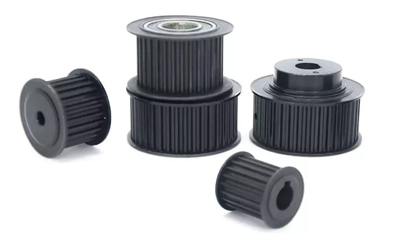
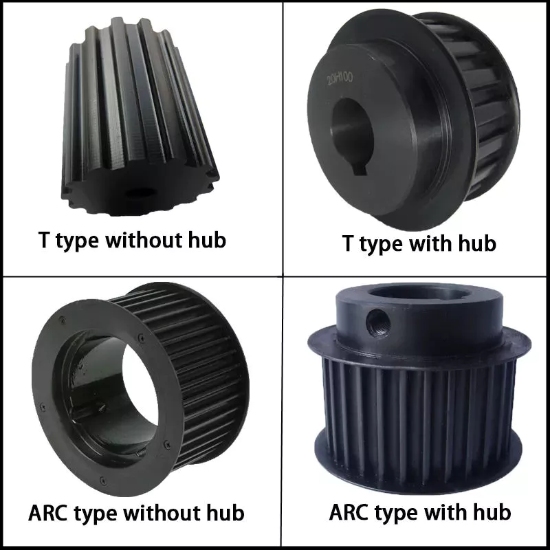
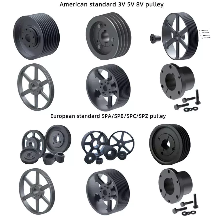
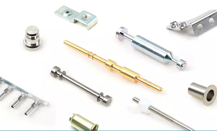
Product Description
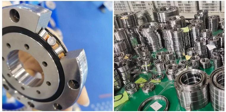
Product display
Product description:
1-material:
Stainless steel:SS201,SS301,SS303,SS304,SS316,SS416 etc.
Iron:A36,45#,1213,12L14,1215 etc.
Aluminun:AL6061,AL6063,AL6082,AL7075,AL5052 etc.
Copper:C11000,C12000,C36000 etc.
Brass:HPb63,HPb62,HPb61,HPb59,H59,H62,H68,H80 etc.
Steel:mild steel,carbon steel,4140,4340,Q235,Q345B,20#,45# etc.
Plastic:ABS,PP,PEI,Peek,PE,POM,Delrin,Nylon,Teflon etc.
2-Parameter
3/4/5-axis CNCmilling,CNC Turning,dilling etc.
Precision:CNC turning ±0.003mm,CNC Milling ±0.01mm
Test equipment:Project,CMM,Altimeter,Micrometer,Thread Gages,Calipers,Pin Gauge etc.
Drawing Format:IGS,STP,X-T,DXF,Pro/E,PDFA
Workable size: CNC turning :φ0.5-φ300*750mm,CNC milling:510*1571*500mm(max).
3-Finishing:Chrome plating,Nickle plating,Tin plating,Zinc plating,Polishing,Anodizing,Power-coating,Oxide black.electroless nickel etc.
4-OEM&ODM are welcome.welcome to processing by drawing and sample.we have powerful equipment to support the processing of products.The main equipment:Machining Center,CNC,Lathe,Turning machine,Milling machine,Drilling machine,Internal and external grinding machine,Cylindrical grinding machine,Tapping drilling machine,Wire cutting machine etc.
5-Delivery time:5-25days after the confirmation of sample(according to order quatity.)
The mode of transportation:Express,by sea or by air(according to customer needs)
Parking:carton/wooden box/other
12 years more experienced engineers team and well trained sales team to support every project.We need long-term customers,excellent products quality and competitive price are our basic to achieve it.
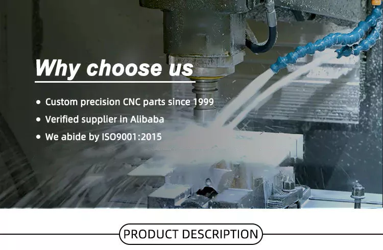
why choose us?because we are professional.Place your order and we’ll take care of the rest.
Thank you.
|
US $1-65 / Piece | |
5 Pieces (Min. Order) |
###
| After-sales Service: | Ensure That The Design Meets The Requirements |
|---|---|
| Warranty: | Ensure That The Design Meets The Requirements |
| Application: | Metal/Stainless Steel/Aluminum Alloy/Plastic/Other |
| Process Usage: | Metal-Cutting CNC Machine Tools, CNC Non-Conventional Machine Tools, Metal-Forming CNC Machine Tools |
| Movement Method: | Linear Control |
| Control Method: | Closed-Loop Control |
###
| Samples: |
US$ 50/Piece
1 Piece(Min.Order) |
|---|
###
| Customization: |
Available
|
|---|
|
US $1-65 / Piece | |
5 Pieces (Min. Order) |
###
| After-sales Service: | Ensure That The Design Meets The Requirements |
|---|---|
| Warranty: | Ensure That The Design Meets The Requirements |
| Application: | Metal/Stainless Steel/Aluminum Alloy/Plastic/Other |
| Process Usage: | Metal-Cutting CNC Machine Tools, CNC Non-Conventional Machine Tools, Metal-Forming CNC Machine Tools |
| Movement Method: | Linear Control |
| Control Method: | Closed-Loop Control |
###
| Samples: |
US$ 50/Piece
1 Piece(Min.Order) |
|---|
###
| Customization: |
Available
|
|---|
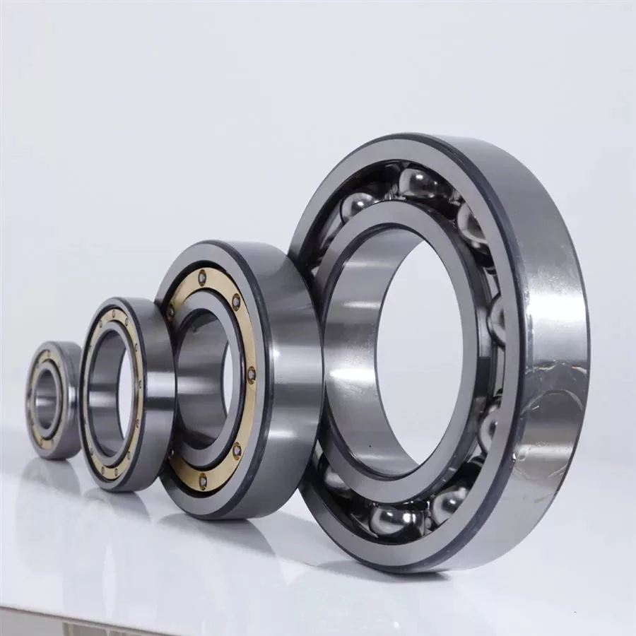
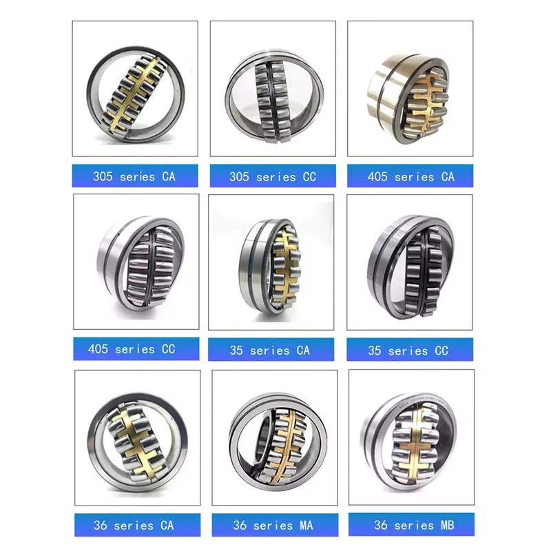
Types of Ball Bearings
In their most basic form, Ball Bearings have one common feature – they are made of steel. The majority of these bearings are made of 52100 steel, which has one percent chromium and one percent carbon. The steel can be hardened by heat trea
tment. 440C stainless steel is used for rusting problems. A cage around the ball balls is traditionally made from thin steel. However, some bearings use molded plastic cages to save money and friction.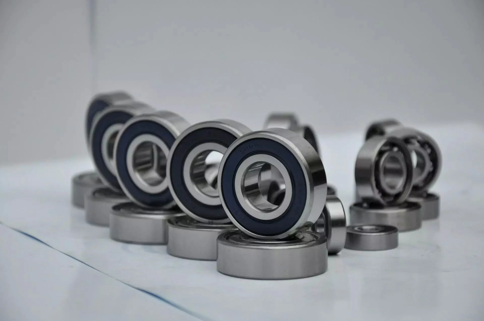
Single-row designs
Steel linear translation stages often use single-row designs for ball bearings. These types of bearings provide smooth linear travel and can withstand high loads. The material steel has a high modulus of elasticity and a high stiffness, as well as a lower thermal expansion than aluminum. For these reasons, steel is the material of choice for a ball bearing in a typical user environment. Single-row designs for ball bearings are also suitable for applications in humid or corrosive environments.
Single-row designs for ball bearings are available in a variety of sizes and are axially adjustable. They have a high radial capacity, but require relatively little space. Single-row deep groove ball bearings with snap rings are STN 02 4605 or R47, respectively. Bearings with snap rings are identified by a suffix such as NR. They may not have seals or shields installed.
These single-row angular contact ball bearings are capable of supporting axial and radial loads. In a two-raceway arrangement, the radial load on bearing A causes a radial load to act on bearing B. Both axial and radial forces are transmitted between single-row angular contact ball bearings, and the resulting internal force must be taken into account to calculate equivalent dynamic bearing loads P.
Single-row deep groove ball bearings are the most common type of ball bearings. These bearings are designed with only one row of rolling elements. The single-row design is simple and durable, which makes it ideal for high-speed applications. Single-row designs for ball bearings are also available in various bore sizes. They can also come in a variety of shapes and are non-separable. If you need a high-speed bearing, you may want to opt for a double-row design.
In addition to single-row designs for ball bearings, you can choose ceramic or steel ball bearings. Ceramic balls are considerably harder than steel balls, but they are not as hard as steel. Hence, ceramic bearings are stiffer than steel ball bearings, resulting in increased stress on the outer race groove and lower load capacity. This is a great benefit for those who need the bearings to be lightweight and strong.
The difference between single-row and double-row designs is in the way that the inner and outer ring are installed. A single-row design places the inner ring in an eccentric position relative to the outer ring. The two rings are in contact at one point, which causes a large gap in the bearing. The balls are then inserted through the gap. As a result, the balls are evenly distributed throughout the bearing, which forces the inner and outer rings to become concentric.
Deep-groove ball bearings are one of the most popular types of ball bearings. They are available in different designs, including snap-ring, seal and shield arrangements. The race diameter of a deep-groove ball bearing is close to the ball’s diameter. These types of bearings are suited for heavy loads, and their axial and radial support are excellent. Their main drawback is that the contact angle cannot be adjusted to accommodate a wide range of relative loads.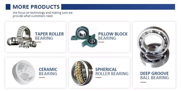
Ceramic hybrid ball bearings
Hybrid ball bearings with ceramic balls have numerous advantages. They feature improved kinematic behavior and require less lubrication. Consequently, they can reduce operating costs. Additionally, their low thermal expansion coefficient allows for smaller changes in contact angle and preload variations, and they can retain tolerances. Furthermore, ceramic hybrid ball bearings have significantly increased life spans compared to conventional steel-steel ball bearings, with up to 10 times the lifespan.
Although ceramic bearings can be used in automotive applications, many people believe that they’re a poor choice for bicycle hubs. They don’t reduce weight and only work well in high-rpm environments. As a result, many cyclists don’t even bother with ceramic-based bearings. However, both Paul Lew and Alan are of the opinion that ceramic bearings are best suited for industrial or medical equipment applications. Furthermore, Paul and Alan believe that they are ideal for high-altitude drone motors.
Another advantage of ceramic hybrid ball bearings is that they use less friction than conventional steel-based balls. They are also more durable, requiring less lubrication than steel-based bearings. Furthermore, the lower friction and rolling resistance associated with ceramic-based ball bearings means that they can last ten times longer than steel-based bearings. A ceramic-based hybrid ball bearing can be used for applications where speed and lubrication are critical.
Ceramic hybrid ball bearings feature both steel and silicon nitride balls. Silicon nitride balls have 50% more modulus of elasticity than steel balls and can improve accuracy and precision. Ceramic balls also have a smoother surface finish than steel balls, which reduces vibration and spindle deflection. These benefits result in increased speed and improved production quality. In addition to this, ceramic balls can also reduce the operating temperature, enhancing the work environment.
Hybrid bearings are a popular alternative to steel bearings. They have some benefits over traditional steel bearings, and are becoming a popular choice for engineered applications. Hybrid bearings are ideal for high speed machines. The material used to manufacture ceramic balls is a high-quality alloy, and is comparatively inexpensive. But you must understand that lubrication is still necessary for hybrid bearings. If you are not careful, you may end up wasting money.
These ball bearings can be used in many industries and applications, and they are widely compatible with most metals. The main advantage of hybrid ball bearings is that they are very durable. While steel balls tend to corrode and wear out, ceramic ball bearings can withstand these conditions while minimizing maintenance and replacement costs. The benefits of hybrid ball bearings are clear. So, consider switching to these newer types of ball bearings.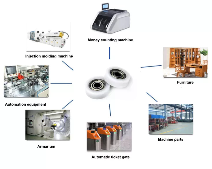
Self-aligning ball bearings
Self-aligning ball bearings are a good choice for many applications. They are a great alternative to traditional ball bearings, and they are ideal for rotating applications in which the shaft must move in several directions. They are also ideal for use in rotating parts where a tight tolerance is necessary. You can choose between two types: plain and flex shaft. Read on to find out which one will suit your needs.
Self-aligning ball bearings are designed with a higher axial load carrying capacity than single-row radial deep groove ball bearings. The amount of axial load carrying capacity is dependent upon the pressure angle. These bearings have a hollow raceway in the outer ring that allows the inner ring to pivot without friction. They are often used for high-speed applications. Because of their design, they are highly accurate.
Self-aligning ball bearings are radial bearings that feature two rows of balls in a spherical outer ring. They also feature two deep uninterrupted raceway grooves in the inner ring. Their unique features make them an excellent choice for applications where shaft deflection is a significant factor. Despite their small size, they have a high level of precision and can withstand heavy loads.
Self-aligning ball bearings can compensate for misalignment in shaft applications. The inner ring and ball assembly are positioned inside an outer ring containing a curved raceway. This spherical design allows the balls and cage to deflect and re-align around the bearing center. These bearings are also ideal for applications where shaft deflection is significant, such as in simple woodworking machinery.
Another type of self-aligning ball bearing uses a common concave outer race. Both balls and outer races automatically compensate for angular misalignment caused by machining, assembly, and deflections. Compared to spherical rollers, they have lower frictional losses than their spherical counterparts. Self-alignment ball bearings also have lower vibration levels compared to other types of bearings.
Self-aligning ball bearings operate in misaligned applications because their spherical outer raceway can accommodate misalignment. This design allows them to work in applications where shaft deflection or housing deformation is common. They are therefore more suitable for low to medium-sized loads. The only real drawback to self-aligning ball bearings is their price. If you need to purchase a self-aligning ball bearing for your next project, you can expect to pay around $1500.


editor by czh 2022-11-28