Tag Archives: tractor parts near me

China Best Sales OEM Precision Custom Parts CNC Machining Tractor Stainless Aluminum Brass Parts near me manufacturer

Product Description

LCH(HangZhou WeiHangZhoug Precision Metal Co., Ltd.)was found in 2008,with a total investment of $1.5 million,over 4,500 square meters,equiped with the most advanced high precision CNC Milling machine(30sets), CNC  turning machine(32sets),CNC machining center,automatic lathe and various kinds of secondary processing equipment more than 80 sets.

Don’t hesitate to contact us,best Price best quality best service to you.

Customize various parts with CNC turning/CNC milling/CNC lathe/Casting parts( OEM & ODM)

Send us 3D drawing,we will help make it true!!!
 

1.Aluminum/Brass/ stainless steel Precision Product 2.Extrusion/ Profile
3.Hardware 4.Injection molding
5.Aluminum Frame 6.Furniture Part
7.Aluminum Office and Living Product 8.CNC Precision Milling Part
9.CNC Precision Turning Part 10.Punch& Stamping& Stretching& Riveting& Assembly
11.Die Casting& Welding& Forging& Bending Part 12.Medical Aluminum Part
13.Aluminum Pipe 14.Large Cross-section/ High Challenge Heat Sink
15.Mechanical Industrial product/ Auto Part 16.LED Aluminum Accessory
17.Mold Design and Manufacture 18.Surface treatment

1.We are True manufacture with competitive price and fast lead time.

2.we have 2 platform:alibaba & made in China,Rich export experience.

3.High quality and best services,Advanced equipment & Professional experience.
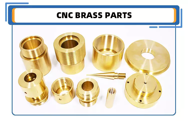
Product Description

High Precision! High-End Finish! Excellent Quality! Best Machining!

(1).Material:Brass/ aluminum/iron/Tin/ stainless steel
(2).Surface Finished: Anodize &Sandblasting
(3).Process: CNC Turning
(4).Tolerance:0.02mm

Parts Information:
(1). Applicable Material—Aluminum/zinc alloy, iron, steel alloy, plastic, brass, steel, and stainless steel
(2). Surface treatment—polishing, zinc plating, nickel plating, chrome plating, anodizing.
(3). Payment Terms: 40% deposit before production and 60% balance before arrange shipping                                                           
(4). Packaging: Standard package/ Pallet or container/ as per customized specifications.
(5). Shipment Terms: Express & air freight is preferred / sea freight/ as per customized specifications.

We have  professional engineers,advanced equipment.more than 5, 000sqm workshop and about 60 sets CNC turning and milling machine make us a modernized and standardized factory. Now we have more than 100 workers, and 5 engineers, as well as 26 professional technicians. Our well-equipped CNC machine workshop has a comprehensive range of precision machining center, milling and turning equipment, all using CNC technology, which enables us to meet the exacting demands of our customers

How we can keep the high quality parts always?

1.All our material will be tested by SGS before production

2. Full control of process:
(1).During the part production,our QC worker will inspect the part size every 1 hour,this will help us to keep the correct tolerance during production
(2). When the parts machining finished,they will be arranged to have surface finished(such as anodize or powder coated),after that,our QC worker will inspect the parts again,because after surface finished,part tolerance may be difference sometimes,if there is any defective parts we found,we will pick them out directly
(3). Before shipping,our package worker will check the part surface and see if there is any scrach or any other thing that affect the part looking,if yes,pick them out.

Customer comments

Conclusion
Thanks for your kind attention, looking forward to your inquiry and we ensure tip top quality products with the best lead-time being provided!any questions just feel free to ask me.Welcome to our factory,best wishes to you!


How to Compare Different Types of Spur Gears

When comparing different types of spur gears, there are several important considerations to take into account. The main considerations include the following: Common applications, Pitch diameter, and Addendum circle. Here we will look at each of these factors in more detail. This article will help you understand what each type of spur gear can do for you. Whether you’re looking to power an electric motor or a construction machine, the right gear for the job will make the job easier and save you money in the long run.
Gear

Common applications

Among its many applications, a spur gear is widely used in airplanes, trains, and bicycles. It is also used in ball mills and crushers. Its high speed-low torque capabilities make it ideal for a variety of applications, including industrial machines. The following are some of the common uses for spur gears. Listed below are some of the most common types. While spur gears are generally quiet, they do have their limitations.
A spur gear transmission can be external or auxiliary. These units are supported by front and rear casings. They transmit drive to the accessory units, which in turn move the machine. The drive speed is typically between 5000 and 6000 rpm or 20,000 rpm for centrifugal breathers. For this reason, spur gears are typically used in large machinery. To learn more about spur gears, watch the following video.
The pitch diameter and diametral pitch of spur gears are important parameters. A diametral pitch, or ratio of teeth to pitch diameter, is important in determining the center distance between 2 spur gears. The center distance between 2 spur gears is calculated by adding the radius of each pitch circle. The addendum, or tooth profile, is the height by which a tooth projects above the pitch circle. Besides pitch, the center distance between 2 spur gears is measured in terms of the distance between their centers.
Another important feature of a spur gear is its low speed capability. It can produce great power even at low speeds. However, if noise control is not a priority, a helical gear is preferable. Helical gears, on the other hand, have teeth arranged in the opposite direction of the axis, making them quieter. However, when considering the noise level, a helical gear will work better in low-speed situations.

Construction

The construction of spur gear begins with the cutting of the gear blank. The gear blank is made of a pie-shaped billet and can vary in size, shape, and weight. The cutting process requires the use of dies to create the correct gear geometry. The gear blank is then fed slowly into the screw machine until it has the desired shape and size. A steel gear blank, called a spur gear billet, is used in the manufacturing process.
A spur gear consists of 2 parts: a centre bore and a pilot hole. The addendum is the circle that runs along the outermost points of a spur gear’s teeth. The root diameter is the diameter at the base of the tooth space. The plane tangent to the pitch surface is called the pressure angle. The total diameter of a spur gear is equal to the addendum plus the dedendum.
The pitch circle is a circle formed by a series of teeth and a diametrical division of each tooth. The pitch circle defines the distance between 2 meshed gears. The center distance is the distance between the gears. The pitch circle diameter is a crucial factor in determining center distances between 2 mating spur gears. The center distance is calculated by adding the radius of each gear’s pitch circle. The dedendum is the height of a tooth above the pitch circle.
Other considerations in the design process include the material used for construction, surface treatments, and number of teeth. In some cases, a standard off-the-shelf gear is the most appropriate choice. It will meet your application needs and be a cheaper alternative. The gear will not last for long if it is not lubricated properly. There are a number of different ways to lubricate a spur gear, including hydrodynamic journal bearings and self-contained gears.
Gear

Addendum circle

The pitch diameter and addendum circle are 2 important dimensions of a spur gear. These diameters are the overall diameter of the gear and the pitch circle is the circle centered around the root of the gear’s tooth spaces. The addendum factor is a function of the pitch circle and the addendum value, which is the radial distance between the top of the gear tooth and the pitch circle of the mating gear.
The pitch surface is the right-hand side of the pitch circle, while the root circle defines the space between the 2 gear tooth sides. The dedendum is the distance between the top of the gear tooth and the pitch circle, and the pitch diameter and addendum circle are the 2 radial distances between these 2 circles. The difference between the pitch surface and the addendum circle is known as the clearance.
The number of teeth in the spur gear must not be less than 16 when the pressure angle is 20 degrees. However, a gear with 16 teeth can still be used if its strength and contact ratio are within design limits. In addition, undercutting can be prevented by profile shifting and addendum modification. However, it is also possible to reduce the addendum length through the use of a positive correction. However, it is important to note that undercutting can happen in spur gears with a negative addendum circle.
Another important aspect of a spur gear is its meshing. Because of this, a standard spur gear will have a meshing reference circle called a Pitch Circle. The center distance, on the other hand, is the distance between the center shafts of the 2 gears. It is important to understand the basic terminology involved with the gear system before beginning a calculation. Despite this, it is essential to remember that it is possible to make a spur gear mesh using the same reference circle.

Pitch diameter

To determine the pitch diameter of a spur gear, the type of drive, the type of driver, and the type of driven machine should be specified. The proposed diametral pitch value is also defined. The smaller the pitch diameter, the less contact stress on the pinion and the longer the service life. Spur gears are made using simpler processes than other types of gears. The pitch diameter of a spur gear is important because it determines its pressure angle, the working depth, and the whole depth.
The ratio of the pitch diameter and the number of teeth is called the DIAMETRAL PITCH. The teeth are measured in the axial plane. The FILLET RADIUS is the curve that forms at the base of the gear tooth. The FULL DEPTH TEETH are the ones with the working depth equal to 2.000 divided by the normal diametral pitch. The hub diameter is the outside diameter of the hub. The hub projection is the distance the hub extends beyond the gear face.
A metric spur gear is typically specified with a Diametral Pitch. This is the number of teeth per inch of the pitch circle diameter. It is generally measured in inverse inches. The normal plane intersects the tooth surface at the point where the pitch is specified. In a helical gear, this line is perpendicular to the pitch cylinder. In addition, the pitch cylinder is normally normal to the helix on the outside.
The pitch diameter of a spur gear is typically specified in millimeters or inches. A keyway is a machined groove on the shaft that fits the key into the shaft’s keyway. In the normal plane, the pitch is specified in inches. Involute pitch, or diametral pitch, is the ratio of teeth per inch of diameter. While this may seem complicated, it’s an important measurement to understand the pitch of a spur gear.
gear

Material

The main advantage of a spur gear is its ability to reduce the bending stress at the tooth no matter the load. A typical spur gear has a face width of 20 mm and will fail when subjected to 3000 N. This is far more than the yield strength of the material. Here is a look at the material properties of a spur gear. Its strength depends on its material properties. To find out what spur gear material best suits your machine, follow the following steps.
The most common material used for spur gears is steel. There are different kinds of steel, including ductile iron and stainless steel. S45C steel is the most common steel and has a 0.45% carbon content. This type of steel is easily obtainable and is used for the production of helical, spur, and worm gears. Its corrosion resistance makes it a popular material for spur gears. Here are some advantages and disadvantages of steel.
A spur gear is made of metal, plastic, or a combination of these materials. The main advantage of metal spur gears is their strength to weight ratio. It is about 1 third lighter than steel and resists corrosion. While aluminum is more expensive than steel and stainless steel, it is also easier to machine. Its design makes it easy to customize for the application. Its versatility allows it to be used in virtually every application. So, if you have a specific need, you can easily find a spur gear that fits your needs.
The design of a spur gear greatly influences its performance. Therefore, it is vital to choose the right material and measure the exact dimensions. Apart from being important for performance, dimensional measurements are also important for quality and reliability. Hence, it is essential for professionals in the industry to be familiar with the terms used to describe the materials and parts of a gear. In addition to these, it is essential to have a good understanding of the material and the dimensional measurements of a gear to ensure that production and purchase orders are accurate.

China Best Sales OEM Precision Custom Parts CNC Machining Tractor Stainless Aluminum Brass Parts     near me manufacturer China Best Sales OEM Precision Custom Parts CNC Machining Tractor Stainless Aluminum Brass Parts     near me manufacturer

China Standard China Belarus Mtz Tractor Spare Parts near me manufacturer

Product Description

China Belarus Mtz Tractor Spare Parts

Product Description

1. Precision CNC machining parts strictly follow customers’ drawing, packing, and quality requirements.
2. Tolerance: between+/-0.01mm;
3. The high-tech CMM inspector to ensure the quality;
4. Full-Experienced engineers and well professional trained workers;
5. Fast delivery time;
6. Professional advice for our customers; 

Detailed Photos


Product Parameters

Our advantage of cnc machining:

Business Type Beyond the Manufacturer and strong organized ability in the industrial
Benefits 1. Deeper industrial experience at CNC machining parts service for more than 10-years,our customer’s requirement is our 1st priority.
2. 2D or 3D files is available;
3. We trust the quality priority and we insist the good quality should be based on the customers’ satisfied;
4. Without any MOQ requirement;
5.Faster delivery time;
6. Customized size and specification /OEM available
7. Near ZheJiang Port

The material

 
 Materials Accept
 
Stainless Steel SS201, SS303, SS304, SS316 etc.
Steel Q235, 20#, 45#,
Brass C36000 ( C26800), C37700 ( HPb59), C38500( HPb58), C27200(CuZn37) , C28000(CuZn40)
Iron 1213, 12L14,1215 etc.
Bronze C51000, C52100, C54400, etc.
Aluminum Al6061, Al6063,AL7075,AL5052 etc
Plastic ABS,POM,PC(Poly-Carbonate),PC+GF,PA(nylon),PA+GF,
PMMA(acrylic)PEEK,PEI etc)

Packaging & Shipping


  1. We prefer DHL or TNT express or other air freight between 1kg-100kg.
  2. we prefer sea freight more than 100kg or more than 1CBM
  3. As per customized specifications.


Company Profile

About us
HangZhou Emitech Technology Co.,Ltd is located in HangZhou City, ZheJiang  Province, Which closed the ZheJiang .The Emitech Technology is mainly engaged in the CNC Machinery Industrial Service for 15 years. Our Parts are sold to Europe, America, Japan, South Korea and China in various kinds of industrial.At present, Our company has CNC Turning machines and CNC centers and equip with professional quality and testing instruments.We have full OEM Experience from worldwide, providing them with One-stop solutions for a broad range of applications.We look forward to cooperating with you!


Our Advantages

1. Precision CNC machining parts strictly follow customer’s drawing,packing and quality requirement.
2. Tolerance: between+/-0.01mm;
3. The high-tech CMM inspector to ensure the quality;
4. Full-Experienced engineers and well professional trained workers;
5. Fast delivery time;
6. Professional advice for our customers; 

After Sales Service

Precision Custom Aluminum Parts machining manufacturer
We usually provide 12 Months repair service. If our duty, we will respond to send the new parts.

Our Service


Our Processing CNC center, CNC milling, CNC turning, drilling, grinding, bending, stamping, tapping,
Surface finish Polishing, sandblasting, Zinc-plated, nickel-plated, chrome-plated, silver-plated, gold-plated, imitation gold-plated,
Tolerance 0.05mm~0.1mm
QC System 100% inspection before shipment
Drawing format CAD / PDF/ DWG/ IGS/ STEP
Packaging Plastic bag/Standard package / Carton or Pallet / As per customized specifications
Payment Terms 30 -50%T/T in advance, 70-50% balance before delivery; Pay Pal or Western Union is acceptable.
Trade terms EXW, FOB, CIF, As per the customer’s request
Shipment Terms

1)We prefer DHL or TNT express or other air freight between 1kg-100kg.

2) we prefer sea freight more than 100kg or more than 1CBM
3) As per customized specifications.

Note The CNC machining parts are usually custom-made based on the customer’s drawings and samples. So we need the Down Payment


Analytical Approaches to Estimating Contact Pressures in Spline Couplings

A spline coupling is a type of mechanical connection between 2 rotating shafts. It consists of 2 parts – a coupler and a coupling. Both parts have teeth which engage and transfer loads. However, spline couplings are typically over-dimensioned, which makes them susceptible to fatigue and static behavior. Wear phenomena can also cause the coupling to fail. For this reason, proper spline coupling design is essential for achieving optimum performance.
splineshaft

Modeling a spline coupling

Spline couplings are becoming increasingly popular in the aerospace industry, but they operate in a slightly misaligned state, causing both vibrations and damage to the contact surfaces. To solve this problem, this article offers analytical approaches for estimating the contact pressures in a spline coupling. Specifically, this article compares analytical approaches with pure numerical approaches to demonstrate the benefits of an analytical approach.
To model a spline coupling, first you create the knowledge base for the spline coupling. The knowledge base includes a large number of possible specification values, which are related to each other. If you modify 1 specification, it may lead to a warning for violating another. To make the design valid, you must create a spline coupling model that meets the specified specification values.
After you have modeled the geometry, you must enter the contact pressures of the 2 spline couplings. Then, you need to determine the position of the pitch circle of the spline. In Figure 2, the centre of the male coupling is superposed to that of the female spline. Then, you need to make sure that the alignment meshing distance of the 2 splines is the same.
Once you have the data you need to create a spline coupling model, you can begin by entering the specifications for the interface design. Once you have this data, you need to choose whether to optimize the internal spline or the external spline. You’ll also need to specify the tooth friction coefficient, which is used to determine the stresses in the spline coupling model 20. You should also enter the pilot clearance, which is the clearance between the tip 186 of a tooth 32 on 1 spline and the feature on the mating spline.
After you have entered the desired specifications for the external spline, you can enter the parameters for the internal spline. For example, you can enter the outer diameter limit 154 of the major snap 54 and the minor snap 56 of the internal spline. The values of these parameters are displayed in color-coded boxes on the Spline Inputs and Configuration GUI screen 80. Once the parameters are entered, you’ll be presented with a geometric representation of the spline coupling model 20.

Creating a spline coupling model 20

The spline coupling model 20 is created by a product model software program 10. The software validates the spline coupling model against a knowledge base of configuration-dependent specification constraints and relationships. This report is then input to the ANSYS stress analyzer program. It lists the spline coupling model 20’s geometric configurations and specification values for each feature. The spline coupling model 20 is automatically recreated every time the configuration or performance specifications of the spline coupling model 20 are modified.
The spline coupling model 20 can be configured using the product model software program 10. A user specifies the axial length of the spline stack, which may be zero, or a fixed length. The user also enters a radial mating face 148, if any, and selects a pilot clearance specification value of 14.5 degrees or 30 degrees.
A user can then use the mouse 110 to modify the spline coupling model 20. The spline coupling knowledge base contains a large number of possible specification values and the spline coupling design rule. If the user tries to change a spline coupling model, the model will show a warning about a violation of another specification. In some cases, the modification may invalidate the design.
In the spline coupling model 20, the user enters additional performance requirement specifications. The user chooses the locations where maximum torque is transferred for the internal and external splines 38 and 40. The maximum torque transfer location is determined by the attachment configuration of the hardware to the shafts. Once this is selected, the user can click “Next” to save the model. A preview of the spline coupling model 20 is displayed.
The model 20 is a representation of a spline coupling. The spline specifications are entered in the order and arrangement as specified on the spline coupling model 20 GUI screen. Once the spline coupling specifications are entered, the product model software program 10 will incorporate them into the spline coupling model 20. This is the last step in spline coupling model creation.
splineshaft

Analysing a spline coupling model 20

An analysis of a spline coupling model consists of inputting its configuration and performance specifications. These specifications may be generated from another computer program. The product model software program 10 then uses its internal knowledge base of configuration dependent specification relationships and constraints to create a valid three-dimensional parametric model 20. This model contains information describing the number and types of spline teeth 32, snaps 34, and shoulder 36.
When you are analysing a spline coupling, the software program 10 will include default values for various specifications. The spline coupling model 20 comprises an internal spline 38 and an external spline 40. Each of the splines includes its own set of parameters, such as its depth, width, length, and radii. The external spline 40 will also contain its own set of parameters, such as its orientation.
Upon selecting these parameters, the software program will perform various analyses on the spline coupling model 20. The software program 10 calculates the nominal and maximal tooth bearing stresses and fatigue life of a spline coupling. It will also determine the difference in torsional windup between an internal and an external spline. The output file from the analysis will be a report file containing model configuration and specification data. The output file may also be used by other computer programs for further analysis.
Once these parameters are set, the user enters the design criteria for the spline coupling model 20. In this step, the user specifies the locations of maximum torque transfer for both the external and internal spline 38. The maximum torque transfer location depends on the configuration of the hardware attached to the shafts. The user may enter up to 4 different performance requirement specifications for each spline.
The results of the analysis show that there are 2 phases of spline coupling. The first phase shows a large increase in stress and vibration. The second phase shows a decline in both stress and vibration levels. The third stage shows a constant meshing force between 300N and 320N. This behavior continues for a longer period of time, until the final stage engages with the surface.
splineshaft

Misalignment of a spline coupling

A study aimed to investigate the position of the resultant contact force in a spline coupling engaging teeth under a steady torque and rotating misalignment. The study used numerical methods based on Finite Element Method (FEM) models. It produced numerical results for nominal conditions and parallel offset misalignment. The study considered 2 levels of misalignment – 0.02 mm and 0.08 mm – with different loading levels.
The results showed that the misalignment between the splines and rotors causes a change in the meshing force of the spline-rotor coupling system. Its dynamics is governed by the meshing force of splines. The meshing force of a misaligned spline coupling is related to the rotor-spline coupling system parameters, the transmitting torque, and the dynamic vibration displacement.
Despite the lack of precise measurements, the misalignment of splines is a common problem. This problem is compounded by the fact that splines usually feature backlash. This backlash is the result of the misaligned spline. The authors analyzed several splines, varying pitch diameters, and length/diameter ratios.
A spline coupling is a two-dimensional mechanical system, which has positive backlash. The spline coupling is comprised of a hub and shaft, and has tip-to-root clearances that are larger than the backlash. A form-clearance is sufficient to prevent tip-to-root fillet contact. The torque on the splines is transmitted via friction.
When a spline coupling is misaligned, a torque-biased thrust force is generated. In such a situation, the force can exceed the torque, causing the component to lose its alignment. The two-way transmission of torque and thrust is modeled analytically in the present study. The analytical approach provides solutions that can be integrated into the design process. So, the next time you are faced with a misaligned spline coupling problem, make sure to use an analytical approach!
In this study, the spline coupling is analyzed under nominal conditions without a parallel offset misalignment. The stiffness values obtained are the percentage difference between the nominal pitch diameter and load application diameter. Moreover, the maximum percentage difference in the measured pitch diameter is 1.60% under a torque of 5000 N*m. The other parameter, the pitch angle, is taken into consideration in the calculation.

China Standard China Belarus Mtz Tractor Spare Parts     near me manufacturer China Standard China Belarus Mtz Tractor Spare Parts     near me manufacturer

China high quality CZPT Tractor Hydraulic Pump F0nn600bb Tractor Parts near me supplier

Product Description

FORD Tractor Hydraulic Pump F0NN6
Ford Tractor: 5610, 5640, 6610, 6640, 6810, 7610, 7740, 7840, 8240, 8340

We also support CASE IH, FIAT, FORD, JOHNDEERE, KUBOTA, MF Tractor OEM Pumps, Steering units.

1. OEM quality.
2. Advantage price.
3. Fast delivery.
4. Warranty quality.
5. Support retail and wholesale.
6. Diversified payment methods.
 

Foed Tractor OEM Paump

D0NN6

D8NN6

D8NN6

E1NN6

D0NN6

D8NN6

E6NN3K514AB, 83960261

E6NN3K514EA, 87559440

D5NN6

E6NN3K514PA

E9NN6

82988360

We insist: nobody has, we have; somebody has, we have better.
We embrace: user is priority, quality is priority, service is priority.
We expect: share the fruit of development, create brilliant career, and serve the community together.
Elephant Fluid Power Co.,Ltd Company is willing to start a new journey with you hand in hand!

We are looking for good long business partner and friendship.
If you are interested in our products, please contact me.I’ll give you a favorable quotation.


The benefits of rubber bushings and how they work

If you have experienced increased vibration while driving, you know the importance of replacing the control arm bushings. The resulting metal-to-metal contact can cause annoying driving problems and be a threat to your safety. Over time, the control arm bushings begin to wear out, a process that can be exacerbated by harsh driving conditions and environmental factors. Additionally, larger tires that are more susceptible to bushing wear are also prone to increased vibration transfer, especially for vehicles with shorter sidewalls. Additionally, these plus-sized tires, which are designed to fit on larger rims, have a higher risk of transmitting vibrations through the bushings.
bushing

rubber

Rubber bushings are rubber tubes that are glued into the inner or outer curve of a cylindrical metal part. The rubber is made of polyurethane and is usually prestressed to avoid breaking during installation. In some cases, the material is also elastic, so it can slide. These properties make rubber bushings an integral part of a vehicle’s suspension system. Here are some benefits of rubber bushings and how they work.
Rubber bushings are used to isolate and reduce vibration caused by the movement of the 2 pieces of equipment. They are usually placed between 2 pieces of machinery, such as gears or balls. By preventing vibrations, rubber bushings improve machine function and service life. In addition to improving the overall performance of the machine, the rubber bushing reduces noise and protects the operator from injury. The rubber on the shock absorber also acts as a vibration isolator. It suppresses the energy produced when the 2 parts of the machine interact. They allow a small amount of movement but minimize vibration.
Both rubber and polyurethane bushings have their advantages and disadvantages. The former is the cheapest, but not as durable as polyurethane. Compared to polyurethane, rubber bushings are a better choice for daily commutes, especially long commutes. Polyurethane bushings provide better steering control and road feel than rubber, but can be more expensive than the former. So how do you choose between polyurethane and rubber bushings?

Polyurethane

Unlike rubber, polyurethane bushings resist high stress environments and normal cycling. This makes them an excellent choice for performance builds. However, there are some disadvantages to using polyurethane bushings. Read on to learn about the advantages and disadvantages of polyurethane bushings in suspension applications. Also, see if a polyurethane bushing is suitable for your vehicle.
Choosing the right bushing for your needs depends entirely on your budget and application. Softer bushings have the lowest performance but may have the lowest NVH. Polyurethane bushings, on the other hand, may be more articulated, but less articulated. Depending on your needs, you can choose a combination of features and tradeoffs. While these are good options for everyday use, for racing and hardcore handling applications, a softer option may be a better choice.
The initial hardness of the polyurethane bushing is higher than that of the rubber bushing. The difference between the 2 materials is determined by durometer testing. Polyurethane has a higher hardness than rubber because it does not react to load in the same way. The harder the rubber, the less elastic, and the higher the tear. This makes it an excellent choice for bushings in a variety of applications.

hard

Solid bushings replace the standard bushings on the subframe, eliminating axle clutter. New bushings raise the subframe by 0.59″ (15mm), correcting the roll center. Plus, they don’t create cabin noise. So you can install these bushings even when your vehicle is lowered. But you should consider some facts when installing solid casing. Read on to learn more about these casings.
The stiffest bushing material currently available is solid aluminum. This material hardly absorbs vibrations, but it is not recommended for everyday use. Its stiffness makes it ideal for rail vehicles. The aluminum housing is prone to wear and tear and may not be suitable for street use. However, the solid aluminum bushings provide the stiffest feel and chassis feedback. However, if you want the best performance in everyday driving, you should choose a polyurethane bushing. They have lower friction properties and eliminate binding.
Sturdy subframe bushings will provide more driver feedback. Additionally, it will strengthen the rear body, eliminating any movement caused by the subframe. You can see this structural integration on the M3 and M4 models. The benefits of solid subframe bushings are numerous. They will improve rear-end handling without compromising drivability. So if you plan to install a solid subframe bushing, be sure to choose a solid bushing.
bushing

Capacitor classification

In the circuit, there is a high electric field on both sides of the capacitor grading bushing. This is due to their capacitor cores. The dielectric properties of the primary insulating layer have a great influence on the electric field distribution within the bushing. This article discusses the advantages and disadvantages of capacitor grade bushings. This article discusses the advantages and disadvantages of grading bushings for capacitors in DC power systems.
One disadvantage of capacitor grading bushings is that they are not suitable for higher voltages. Capacitor grading bushings are prone to serious heating problems. This may reduce their long-term reliability. The main disadvantage of capacitor grading bushings is that they increase the radial thermal gradient of the main insulation. This can lead to dielectric breakdown.
Capacitor grading bushing adopts cylindrical structure, which can suppress the influence of temperature on electric field distribution. This reduces the coefficient of inhomogeneity of the electric field in the confinement layer. Capacitor grading bushings have a uniform electric field distribution across their primary insulation. Capacitive graded bushings are also more reliable than nonlinear bushings.
Electric field variation is the most important cause of failure. The electrode extension layer can be patterned to control the electric field to avoid flashover or partial discharge of the primary insulating material. This design can be incorporated into capacitor grading bushings to provide better electric fields in high voltage applications. This type of bushing is suitable for a wide range of applications. This article discusses the advantages and disadvantages of capacitor grade bushings.

Metal

When choosing between plastic and metal sleeves, it is important to choose a product that can handle the required load. Plastic bushings tend to deteriorate and often crack under heavy loads, reducing their mechanical strength and service life. Metal bushings, on the other hand, conduct heat more efficiently, preventing any damage to the mating surfaces. Plastic bushings can also be made with lubricating fillers added to a resin matrix.
Plastic bushings have many advantages over metal bushings, including being cheap and versatile. Plastic bushings are now used in many industries because they are inexpensive and quick to install. These plastic products are also self-lubricating and require less maintenance than metals. They are often used in applications where maintenance costs are high or parts are difficult to access. Also, if they are prone to wear and tear, they are easy to replace.
Metal bushings can be made of PTFE, plastic or bronze and are self-lubricating. Graphite plugs are also available for some metal bushings. Their high load capacity and excellent fatigue resistance make them a popular choice for automotive applications. The bi-metallic sintered bronze layer in these products provides excellent load-carrying capacity and good friction properties. The steel backing also helps reduce processing time and avoids the need for additional pre-lubrication.
bushing

plastic

A plastic bushing is a small ball of material that is screwed onto a nut or locknut on a mechanical assembly. Plastic bushings are very durable and have a low coefficient of friction, making them a better choice for durable parts. Since they do not require lubrication, they last longer and cost less than their metal counterparts. Unlike metal bushings, plastic bushings also don’t scratch or attract dirt.
One type of acetal sleeve is called SF-2. It is made of metal alloy, cold rolled steel and bronze spherical powder. A small amount of surface plastic penetrated into the voids of the copper spherical powder. Plastic bushings are available in a variety of colors, depending on the intended application. SF-2 is available in black or grey RAL 7040. Its d1 diameter is sufficient for most applications.
Another acetal sleeve is UHMW-PE. This material is used in the production of bearings and in low load applications. This material can withstand pressures from 500 to 800 PSI and is widely available. It is also self-lubricating and readily available. Due to its high resistance to temperature and chemical agents, it is an excellent choice for low-load industrial applications. If you’re in the market for an alternative to nylon, consider acetal.
Positional tolerances in many automotive components can cause misalignment. Misaligned plastic bushings can negatively impact the driver’s experience. For example, the cross tubes used to mount the seat to the frame are made by a stamping process. The result is a misalignment that can increase torque. Also, the plastic bushing is pushed to 1 side of the shaft. The increased pressure results in higher friction, which ultimately results in a poor driving experience.
v
China high quality CZPT Tractor Hydraulic Pump F0nn600bb Tractor Parts     near me supplier China high quality CZPT Tractor Hydraulic Pump F0nn600bb Tractor Parts     near me supplier

China OEM Aluminum Part Car Brake Shoe Machine Tractor CZPT Joint Machining Parts Hot Sale near me manufacturer

Product Description

HangZhou CZPT Hardware Machinery Co., Ltd. mainly provides intelligent manufacturing solutions for precision hardware parts for domestic and foreign customers. The company was established in 2008 and currently has more than 60 sets of various high-precision cutting-edge equipment and more than 80 employees in the production system, including There are more than 40 senior technical talents, and a talent directional transfer plan has been signed with a number of technical schools and training centers.
 
The company’s business involves precision parts and hardware processing in many industries such as auto parts, 3C automation equipment, aerospace, construction machinery, medical, food, new energy battery equipment, instrumentation, precision instruments, hardware tools, etc. At the same time, it also provides customers with precision parts. Design and manufacture of fixtures, jigs, mold accessories, processing of special material parts (such as ceramics, cemented carbide) and automation equipment design, installation, debugging, and production equipment maintenance, improvement and other related businesses.

In terms of production, according to the ISO9001:2015 quality management system, we strictly control each link of product production to ensure product performance and quality. At the same time, the company has also established a systematic, scientific and effective international information security management system, from professional And authoritative level to provide customers with information security, so that customers’ products will not have security risks of leakage, so that the delivery cycle is guaranteed.

The company adheres to the corporate tenet of “emphasis on quality, integrity, and responsibility”, with the business philosophy of “customer first, technology, efficiency, and service”. Under the guidance of the “Four Fines” business policy, the company has reached the forefront of the industry in the entire precision parts processing industry.

At present, the company has served nearly 100 customers, 80% of which are well-known enterprises in the industry. At the same time, we have a perfect after-sales service system in the industry, and continue to use a solid technical foundation and strict scientific management system to continuously improve and surpass Customer satisfaction, so that customers feel comfortable before cooperation and rest assured after cooperation.

Our advantage of cnc machining:

Business Type

Manufacturer


Advantage

1. Qida is factory providing CNC machining service for more than 10years, we focus on client’s demand and client’s satisfaction.

2. Provide 2D & 3D drawing for modifying

3. Competitive price with good quality

4. Small order is acceptable

5. Short delivery time (7-25days according to order Qty)

6. Customized size and specification /OEM available

7. Near HangZhou and HangZhou, convenient transportation


Application

.Automobile, motorcycle, medical machinery, electronics, fixtures, automation, etc

Materials Available of CNC Machining:


Materials Available


Stainless Steel

SS201, SS303, SS304, SS316 etc.

Steel

Q235, 20#, 45# etc.cr12mor, 


Brass

C36000 ( C26800), C37700 ( HPb59), C38500( HPb58), C27200(CuZn37) , C28000(CuZn40)

Iron:

1213, 12L14,1215 etc.

Bronze

C51000, C52100, C54400, etc.

Aluminum

Al6061, Al6063,AL7075,AL5052 etc

Better services of CNC machining:

(Payment Terms/Trade Term/Shipment Terms/ ):

Our Processing

CNC machining, CNC milling and turning, drilling, grinding, bending, stamping, tapping, injection
Wire cut

Surface finish

Zinc-plated, nickel-plated, chrome-plated, silver-plated, gold-plated, imitation gold-plated,

Tolerance

0.05mm~0.1mm

QC System

100% inspection before shipment

Drawing format

CAD / PDF/ DWG/ IGS/ STEP

Packaging

Standard package / Carton or Pallet / As per customized specifications

Payment Terms

30 -50%T/T in advance, 70-50% balance before delivery; Pay Pal or Western Union is acceptable.

Trade terms

EXW, FOB, CIF, As per customer’s request


Shipment Terms

1) 0-100kg: express & air freight priority

2) >100kg: sea freight priority

3) As per customized specifications


Note

All cnc machining parts are custom made according to customer’s drawings or samples, no stock.

If you have any cnc machining parts to be made, please feel free to send your kind drawings/samples to us

FAQ:
What is your product range?
1.CNC machining parts, precision parts, CNC parts, metal machining parts.
2.CNC turning parts, CNC turned parts,Lathe parts, turned parts.
3.CNC milling parts, CNC milled parts, metal milling parts.
4.CNC machined parts,CNC machine part, CNC machinery parts.
5.Metal parts, Auto parts, mechanical parts.spare parts,accessories,hardware.
6.Die casting parts,aluminum casting parts, Zinc casting parts.
7.Die stamping parts, metal stamping parts, press stamping tooling
8. Sheet metal fabrication, bending parts, laser cutting parts, welding parts.
 
Are you a manufacturer?
Yes, We are the manufacturer of all kinds of metal parts by CNC machining, turning, milling, stamping,
casting and bending with13 years’experince ,Warmly welcome to visit our factory at any time.
 
What is material you can process?
Stainless steel: SUS303, SUS304, SUS316, SUS316L, SUS430, SUS440, etc
Aluminum: 6061-T6, 6063-T5, 7075-T6, 2011, 2017, 2571, 5052, 5083, 6082 etc
Brass/copper: C11000, C15710, C12000, C26000, C36000, etc
Carbon steel:  Q235,S235JR,1571, 1015, 1571, 1571, 1030, 1035, 1040, 1045, etc
Plastic: PVC, POM, Telfon, Delrin, PEEK ,Nylon, ABS, PC, PP,PA6, PA66, etc
Free cutting steel: 1211, 12L13, 12L14, 1215, etc
Tool Steel: SKD61,SKD11,HSS M2,ASP23 ,H13,1.2344,D2,1.2379,etc
Alloy steel: 40Cr,15CrMo,4140,4340,35CrMo,16MnCr5
Titanium alloy
 
What benefit we can get from you?
1)Competitive price
2)High quality control : 100% full inspection before shipment
3)High precision, tolerance can be ± 0.005mm
4)Fast lead time (5-7days for samples, 12-15 days for mass production)
5)Non-standard//OEM//customized service provided
6)No MOQ, small QTY is acceptable.
7)ISO 9001:2015 certificated factory, ROHS material used
9)Professional export packing: separate Blister plastic box or Bubble Wrap/Pearl Wool +Carton+Wooded Case, keep no scratch and damage
 
How does the CZPT control the quality?
1)During processing, the operating machine worker inspect the each sizes by themselves.
2)After finished the first whole part, will show to QA for full inspection.
3)Before shipment, the QA will inspect according to ISO sampling inspection standard for mass production. Will do 100% full checking for small QTY.
4) when shipping the goods, we will attached the inspection report with the parts.
 
How to handle the complains?
1)During processing, if found any sizes defective, we will inform the clients and get clients approval.
2)If happen any complaints after got the goods, pls show us photos and detail complaints points, we will check with the production department and QC depart. Immediately and give solving solution with 6 hours.
3)If need re-make, we will arrange re-make urgently and ship you new replacement within 5 days. CZPT will bear all the cost ( include shipping cost).
 
What’s the payment term?
50% deposit, 50% balance by T/T before shipment when order amount over 5000USD.
100% T/T in advance when amount less than 5000USD
L/C payment term for big amount order is acceptable.
Paypal and Western Union for samples cost or very small order.
 
 
What’s the delivery time ?
Normal for samples, 5-7 working days;
For mass production, it takes about 12-15 working days.
If any urgent parts, we can provide preferential processing and control the delivery time as you required.
 
What is the standard of package?
Professional export packing:
1)Separate Blister plastic box or Bubble Wrap/Pearl Wool, keep no scratch and damage.
2)Under 100 KGS parts, use strong DHL export Carton .
3)Above 100 KGS, will customize Wooded case for packing.
 
How to ship the parts?
1)Normally, we shipped the goods by DHL,FEDEX,UPS,TNT express.
2-3 days can arrived the clients’ company directly.
2)For heavy parts, can shipped by air or by sea according to customers’indication.
 
Can we get some sample?
1.Free sample can be provided,but the clients will bear the shipping cost.
2.Samplemaking can be satisfied as customer’s demands,and the sample cost is about 50-100 USD for each part,it depends on the processing.
3. Sample charge is returnable after order the mass production.
 
What kind of certificate you have ?
We have ISO9001:2015
RoHS compliance for material and surface treatment
 
What information should i let you know once i want to make a inquiry?
1.The drawings ( PDF,CAD or 3D )?
2. The material for each drawings?
3. The surface treatment requirement.
4. How many pieces do you need?
 
How fast you can get quotation from CZPT ?
After get customer’s detail enquiry( Clear drawings, material, QTY, surface treatment).
Normally, we will provide offer within 6 hours.
If more than 100 drawings, will provide price within 24 hours.
 
What is your main market?
North America, South America, Western European,
Southeast Asia,Australia
 

Guide to Drive Shafts and U-Joints

If you’re concerned about the performance of your car’s driveshaft, you’re not alone. Many car owners are unaware of the warning signs of a failed driveshaft, but knowing what to look for can help you avoid costly repairs. Here is a brief guide on drive shafts, U-joints and maintenance intervals. Listed below are key points to consider before replacing a vehicle driveshaft.
air-compressor

Symptoms of Driveshaft Failure

Identifying a faulty driveshaft is easy if you’ve ever heard a strange noise from under your car. These sounds are caused by worn U-joints and bearings supporting the drive shaft. When they fail, the drive shafts stop rotating properly, creating a clanking or squeaking sound. When this happens, you may hear noise from the side of the steering wheel or floor.
In addition to noise, a faulty driveshaft can cause your car to swerve in tight corners. It can also lead to suspended bindings that limit overall control. Therefore, you should have these symptoms checked by a mechanic as soon as you notice them. If you notice any of the symptoms above, your next step should be to tow your vehicle to a mechanic. To avoid extra trouble, make sure you’ve taken precautions by checking your car’s oil level.
In addition to these symptoms, you should also look for any noise from the drive shaft. The first thing to look for is the squeak. This was caused by severe damage to the U-joint attached to the drive shaft. In addition to noise, you should also look for rust on the bearing cap seals. In extreme cases, your car can even shudder when accelerating.
Vibration while driving can be an early warning sign of a driveshaft failure. Vibration can be due to worn bushings, stuck sliding yokes, or even springs or bent yokes. Excessive torque can be caused by a worn center bearing or a damaged U-joint. The vehicle may make unusual noises in the chassis system.
If you notice these signs, it’s time to take your car to a mechanic. You should check regularly, especially heavy vehicles. If you’re not sure what’s causing the noise, check your car’s transmission, engine, and rear differential. If you suspect that a driveshaft needs to be replaced, a certified mechanic can replace the driveshaft in your car.
air-compressor

Drive shaft type

Driveshafts are used in many different types of vehicles. These include four-wheel drive, front-engine rear-wheel drive, motorcycles and boats. Each type of drive shaft has its own purpose. Below is an overview of the 3 most common types of drive shafts:
The driveshaft is a circular, elongated shaft that transmits torque from the engine to the wheels. Drive shafts often contain many joints to compensate for changes in length or angle. Some drive shafts also include connecting shafts and internal constant velocity joints. Some also include torsional dampers, spline joints, and even prismatic joints. The most important thing about the driveshaft is that it plays a vital role in transmitting torque from the engine to the wheels.
The drive shaft needs to be both light and strong to move torque. While steel is the most commonly used material for automotive driveshafts, other materials such as aluminum, composites, and carbon fiber are also commonly used. It all depends on the purpose and size of the vehicle. Precision Manufacturing is a good source for OEM products and OEM driveshafts. So when you’re looking for a new driveshaft, keep these factors in mind when buying.
Cardan joints are another common drive shaft. A universal joint, also known as a U-joint, is a flexible coupling that allows 1 shaft to drive the other at an angle. This type of drive shaft allows power to be transmitted while the angle of the other shaft is constantly changing. While a gimbal is a good option, it’s not a perfect solution for all applications.
CZPT, Inc. has state-of-the-art machinery to service all types of drive shafts, from small cars to race cars. They serve a variety of needs, including racing, industry and agriculture. Whether you need a new drive shaft or a simple adjustment, the staff at CZPT can meet all your needs. You’ll be back on the road soon!

U-joint

If your car yoke or u-joint shows signs of wear, it’s time to replace them. The easiest way to replace them is to follow the steps below. Use a large flathead screwdriver to test. If you feel any movement, the U-joint is faulty. Also, inspect the bearing caps for damage or rust. If you can’t find the u-joint wrench, try checking with a flashlight.
When inspecting U-joints, make sure they are properly lubricated and lubricated. If the joint is dry or poorly lubricated, it can quickly fail and cause your car to squeak while driving. Another sign that a joint is about to fail is a sudden, excessive whine. Check your u-joints every year or so to make sure they are in proper working order.
Whether your u-joint is sealed or lubricated will depend on the make and model of your vehicle. When your vehicle is off-road, you need to install lubricable U-joints for durability and longevity. A new driveshaft or derailleur will cost more than a U-joint. Also, if you don’t have a good understanding of how to replace them, you may need to do some transmission work on your vehicle.
When replacing the U-joint on the drive shaft, be sure to choose an OEM replacement whenever possible. While you can easily repair or replace the original head, if the u-joint is not lubricated, you may need to replace it. A damaged gimbal joint can cause problems with your car’s transmission or other critical components. Replacing your car’s U-joint early can ensure its long-term performance.
Another option is to use 2 CV joints on the drive shaft. Using multiple CV joints on the drive shaft helps you in situations where alignment is difficult or operating angles do not match. This type of driveshaft joint is more expensive and complex than a U-joint. The disadvantages of using multiple CV joints are additional length, weight, and reduced operating angle. There are many reasons to use a U-joint on a drive shaft.
air-compressor

maintenance interval

Checking U-joints and slip joints is a critical part of routine maintenance. Most vehicles are equipped with lube fittings on the driveshaft slip joint, which should be checked and lubricated at every oil change. CZPT technicians are well-versed in axles and can easily identify a bad U-joint based on the sound of acceleration or shifting. If not repaired properly, the drive shaft can fall off, requiring expensive repairs.
Oil filters and oil changes are other parts of a vehicle’s mechanical system. To prevent rust, the oil in these parts must be replaced. The same goes for transmission. Your vehicle’s driveshaft should be inspected at least every 60,000 miles. The vehicle’s transmission and clutch should also be checked for wear. Other components that should be checked include PCV valves, oil lines and connections, spark plugs, tire bearings, steering gearboxes and brakes.
If your vehicle has a manual transmission, it is best to have it serviced by CZPT’s East Lexington experts. These services should be performed every 2 to 4 years or every 24,000 miles. For best results, refer to the owner’s manual for recommended maintenance intervals. CZPT technicians are experienced in axles and differentials. Regular maintenance of your drivetrain will keep it in good working order.

China OEM Aluminum Part Car Brake Shoe Machine Tractor CZPT Joint Machining Parts Hot Sale     near me manufacturer China OEM Aluminum Part Car Brake Shoe Machine Tractor CZPT Joint Machining Parts Hot Sale     near me manufacturer

China best Casting Stainless Steel Tractor Parts near me factory

Product Description

casting stainless steel tractor parts

    R&D

Softward: Solidworks, CAD,  Procast,  UG

Development cycle of samples: 25-35 days

Materials

Stainless steel: 304/304L, 316/316L, 410/416 etc
Duplex stainless steel: 2250, 2507, Zeron 100 etc
Carbon steel
Alloy steel

Technical Parameter

Part weight: 2g to 30kgs
Max dimension : 600mm for diameter or length
Min wall thickness : 1.5mm
Casting roughness: Ra3.2-6.4       Machining roughness: Ra1.6
Tolerance of casting: CT6
Inner core: ceramic core, urea core, water soluble wax core.

Heat treatment

Normalzing, Tempering, Quenching, Annealing,  Quenching & Tempering, Caburization,    Solution treatment.

Surface treatment

Polishing, bead blasting, zinc plating, hot dip galvanized, nickel plating, passivation,          

Electro-polising, mirror polishing, Brush polishing,  PE coating, Powder coating, etc

Inspection

Cleanliness inspection, X-Ray radiographic inspection, CMM inspection

Production capacity

More than 120 tons per month

Quality Certificates

ISO9001; ISO14001

Company profile:

HangZhou CZPT Foundry Co.,Ltd located in ZheJiang Province, China. 
We specialized in silica sol investment casting with more than 20 years and covers 100,000 square meters
with 500 employees.
Our production management and quality control system fully meet the request of ISO 9001:2015, certified by TUV Rheinland.

Hongsheng Produces a wide variety of high-grade precision casting and machined parts in stainless steel, carbon steel, alloy steel..the main fields including high-speed rail, automobile industry, marine equipment, medical instrument,
machinery parts, construction hardware, pump and valve parts…etc
 

Advantages of Stainless Steel Castings

Stainless steel investment castings are used across a wide range of industry sectors for the following reasons:

  • Excellent Corrosion Resistance: Chromium is used as an alloying element in stainless steel which helps improve its anti-corrosive properties. Unlike carbon and alloy steel, stainless steel castings require little or no additional surface finishing. This 1 reason why stainless steel investment cast parts are used in industrial components such as valves, pumps, and other parts where corrosion resistance is critical.
  • Exceptional Visual Quality: Grade A visual appearance is possible for investment cast parts that require high visual quality.
  • Surface Finishes: 120 RMS or better is easily achieve.
  •  
  • Near Net Shape Parts: Avoid long run time machine parts using near net investment cast parts.
  • Close Tolerances: ±.005 inch per inch tolerance levels can be achieved
  •  


Latest News!!

New wax injection machine set up finished. Max-pressure is 35 tons,wax pattern largest size is 800*600 mm.
It’s the biggest wax injection machine in China. 
With the help of this machine,we are CZPT to cast big steel parts for our customers by silical sol investment casting way.


Secondary Operations and Treatment of Investment Castings We Offer


Polished zinc plating, nickel plating, electroplating, Chrome plating

Anodizing, phosphating, acid treatment, polishing

High precision CNC machining

Broaching, milling, drilling, tapping

Surface grinding, sand blasting, powder coating

Heat treatment

FAQ: 

Q1: What is our payment term?

A:T/T, Paypal. 

Q2: How can we quote for you?

A: Please email us enquiry with all technical drawings you have, such as material grade, tolerance, mechanical

properties, heat treatment, requirements, etc. Our specialized engineers will check and quote for you within 24 hours. 

Q3: Which product are often processed by your company ?
A: Auto parts,machinery part, marine part, Kitchen parts, Agricultural parts.

Q4: Which material are often used ?
 A: Stainless steel. alloy steel, carbon steel, aluminum, copper.

Q5: Which finish you can provide ?
A:Sand blasting, Tumbling, Polishinh, Electro-polishing, Mirror Polishing, Powder coating, Electrophoresis, ETC.

Q6: What is the MOQ ?
 A: Based on the product, normal 100 pcs.

Q7: Can we make the samples?
 A: Is Available, 15-20days for sampling.

Q8: How about for the lead time?
A: Normally about 35 days for mass production, pls inform us if it is urgent order.


How to Calculate Stiffness, Centering Force, Wear and Fatigue Failure of Spline Couplings

There are various types of spline couplings. These couplings have several important properties. These properties are: Stiffness, Involute splines, Misalignment, Wear and fatigue failure. To understand how these characteristics relate to spline couplings, read this article. It will give you the necessary knowledge to determine which type of coupling best suits your needs. Keeping in mind that spline couplings are usually spherical in shape, they are made of steel.
splineshaft

Involute splines

An effective side interference condition minimizes gear misalignment. When 2 splines are coupled with no spline misalignment, the maximum tensile root stress shifts to the left by 5 mm. A linear lead variation, which results from multiple connections along the length of the spline contact, increases the effective clearance or interference by a given percentage. This type of misalignment is undesirable for coupling high-speed equipment.
Involute splines are often used in gearboxes. These splines transmit high torque, and are better able to distribute load among multiple teeth throughout the coupling circumference. The involute profile and lead errors are related to the spacing between spline teeth and keyways. For coupling applications, industry practices use splines with 25 to 50-percent of spline teeth engaged. This load distribution is more uniform than that of conventional single-key couplings.
To determine the optimal tooth engagement for an involved spline coupling, Xiangzhen Xue and colleagues used a computer model to simulate the stress applied to the splines. The results from this study showed that a “permissible” Ruiz parameter should be used in coupling. By predicting the amount of wear and tear on a crowned spline, the researchers could accurately predict how much damage the components will sustain during the coupling process.
There are several ways to determine the optimal pressure angle for an involute spline. Involute splines are commonly measured using a pressure angle of 30 degrees. Similar to gears, involute splines are typically tested through a measurement over pins. This involves inserting specific-sized wires between gear teeth and measuring the distance between them. This method can tell whether the gear has a proper tooth profile.
The spline system shown in Figure 1 illustrates a vibration model. This simulation allows the user to understand how involute splines are used in coupling. The vibration model shows 4 concentrated mass blocks that represent the prime mover, the internal spline, and the load. It is important to note that the meshing deformation function represents the forces acting on these 3 components.
splineshaft

Stiffness of coupling

The calculation of stiffness of a spline coupling involves the measurement of its tooth engagement. In the following, we analyze the stiffness of a spline coupling with various types of teeth using 2 different methods. Direct inversion and blockwise inversion both reduce CPU time for stiffness calculation. However, they require evaluation submatrices. Here, we discuss the differences between these 2 methods.
The analytical model for spline couplings is derived in the second section. In the third section, the calculation process is explained in detail. We then validate this model against the FE method. Finally, we discuss the influence of stiffness nonlinearity on the rotor dynamics. Finally, we discuss the advantages and disadvantages of each method. We present a simple yet effective method for estimating the lateral stiffness of spline couplings.
The numerical calculation of the spline coupling is based on the semi-analytical spline load distribution model. This method involves refined contact grids and updating the compliance matrix at each iteration. Hence, it consumes significant computational time. Further, it is difficult to apply this method to the dynamic analysis of a rotor. This method has its own limitations and should be used only when the spline coupling is fully investigated.
The meshing force is the force generated by a misaligned spline coupling. It is related to the spline thickness and the transmitting torque of the rotor. The meshing force is also related to the dynamic vibration displacement. The result obtained from the meshing force analysis is given in Figures 7, 8, and 9.
The analysis presented in this paper aims to investigate the stiffness of spline couplings with a misaligned spline. Although the results of previous studies were accurate, some issues remained. For example, the misalignment of the spline may cause contact damages. The aim of this article is to investigate the problems associated with misaligned spline couplings and propose an analytical approach for estimating the contact pressure in a spline connection. We also compare our results to those obtained by pure numerical approaches.

Misalignment

To determine the centering force, the effective pressure angle must be known. Using the effective pressure angle, the centering force is calculated based on the maximum axial and radial loads and updated Dudley misalignment factors. The centering force is the maximum axial force that can be transmitted by friction. Several published misalignment factors are also included in the calculation. A new method is presented in this paper that considers the cam effect in the normal force.
In this new method, the stiffness along the spline joint can be integrated to obtain a global stiffness that is applicable to torsional vibration analysis. The stiffness of bearings can also be calculated at given levels of misalignment, allowing for accurate estimation of bearing dimensions. It is advisable to check the stiffness of bearings at all times to ensure that they are properly sized and aligned.
A misalignment in a spline coupling can result in wear or even failure. This is caused by an incorrectly aligned pitch profile. This problem is often overlooked, as the teeth are in contact throughout the involute profile. This causes the load to not be evenly distributed along the contact line. Consequently, it is important to consider the effect of misalignment on the contact force on the teeth of the spline coupling.
The centre of the male spline in Figure 2 is superposed on the female spline. The alignment meshing distances are also identical. Hence, the meshing force curves will change according to the dynamic vibration displacement. It is necessary to know the parameters of a spline coupling before implementing it. In this paper, the model for misalignment is presented for spline couplings and the related parameters.
Using a self-made spline coupling test rig, the effects of misalignment on a spline coupling are studied. In contrast to the typical spline coupling, misalignment in a spline coupling causes fretting wear at a specific position on the tooth surface. This is a leading cause of failure in these types of couplings.
splineshaft

Wear and fatigue failure

The failure of a spline coupling due to wear and fatigue is determined by the first occurrence of tooth wear and shaft misalignment. Standard design methods do not account for wear damage and assess the fatigue life with big approximations. Experimental investigations have been conducted to assess wear and fatigue damage in spline couplings. The tests were conducted on a dedicated test rig and special device connected to a standard fatigue machine. The working parameters such as torque, misalignment angle, and axial distance have been varied in order to measure fatigue damage. Over dimensioning has also been assessed.
During fatigue and wear, mechanical sliding takes place between the external and internal splines and results in catastrophic failure. The lack of literature on the wear and fatigue of spline couplings in aero-engines may be due to the lack of data on the coupling’s application. Wear and fatigue failure in splines depends on a number of factors, including the material pair, geometry, and lubrication conditions.
The analysis of spline couplings shows that over-dimensioning is common and leads to different damages in the system. Some of the major damages are wear, fretting, corrosion, and teeth fatigue. Noise problems have also been observed in industrial settings. However, it is difficult to evaluate the contact behavior of spline couplings, and numerical simulations are often hampered by the use of specific codes and the boundary element method.
The failure of a spline gear coupling was caused by fatigue, and the fracture initiated at the bottom corner radius of the keyway. The keyway and splines had been overloaded beyond their yield strength, and significant yielding was observed in the spline gear teeth. A fracture ring of non-standard alloy steel exhibited a sharp corner radius, which was a significant stress raiser.
Several components were studied to determine their life span. These components include the spline shaft, the sealing bolt, and the graphite ring. Each of these components has its own set of design parameters. However, there are similarities in the distributions of these components. Wear and fatigue failure of spline couplings can be attributed to a combination of the 3 factors. A failure mode is often defined as a non-linear distribution of stresses and strains.

China best Casting Stainless Steel Tractor Parts     near me factory China best Casting Stainless Steel Tractor Parts     near me factory

China Best Sales Agricultural Machinery Tractor Tie Rod End OEM 826852m91 907729m1 969352m1 135 240 250 Tractor Spare Parts near me factory

Product Description

Product Description

Warranty  1 Year Certification TS16949
Color Natural color Application Massey Ferguson
OEM NO. 826852M91  MOQ 100 PCS
Engravement Customized Port HangZhou/ZheJiang

Specifications

1.Supply to USA,Europe,and so on
2.Matrial:Body C45 Ball Pin Cr40
3.Professional Perfomance Auto parts supplier

Detail Images

Other Products

Our Company

Packing & Delivery

Certification

Our Service

1. OEM Manufacturing welcome: Product, Package…
2. Sample order
3. We will reply you for your inquiry in 24 hours.
4. after sending, we will track the products for you once every 2 days, until you get the products. When you got the
goods, test them, and give me a feedback.If you have any questions about the problem, contact with us, we will offer
the solve way for you.

FAQ

Q1. What is your terms of packing?
A: Generally, we pack our goods in neutral white boxes and brown cartons. If you have legally registered patent,
we can pack the goods in your branded boxes after getting your authorization letters.

Q2. What is your terms of payment?
A: T/T 30% as deposit, and 70% before delivery. We’ll show you the photos of the products and packages
before you pay the balance.

Q3. What is your terms of delivery?
A: EXW, FOB, CFR, CIF, DDU.

Q4. How about your delivery time?
A: Generally, it will take 30 to 60 days after receiving your advance payment. The specific delivery time depends
on the items and the quantity of your order.

Q5. Can you produce according to the samples?
A: Yes, we can produce by your samples or technical drawings. We can build the molds and fixtures.

Q6. What is your sample policy?
A: We can supply the sample if we have ready parts in stock, but the customers have to pay the sample cost and
the courier cost.

Q7. Do you test all your goods before delivery?
A: Yes, we have 100% test before delivery

Q8: How do you make our business long-term and good relationship?
A:1. We keep good quality and competitive price to ensure our customers benefit ;
2. We respect every customer as our friend and we sincerely do business and make friends with them,
no matter where they come from.

Axle Spindle Types and Features

The axle spindle is an integral part of your vehicle’s suspension. There are several different types and features, including mounting methods, bearings, and functions. Read on for some basic information on axle spindles. The next part of the article will cover how to choose the correct axle spindle for your vehicle. This article will also discuss the different types of spindles available, including the differences between the rear and front bearings.
Driveshaft

Features

The improved axle spindle nut assembly is capable of providing additional performance benefits, including increased tire life and reduced seal failure. Its keyway features and radially inwardly extending teeth allow nut adjustment to be accomplished with precision. The invention further provides a unique, multi-piece locking mechanism that minimizes leakage and torque transfer. Its principles and features are detailed in the appended claims. For example, the improved axle spindle nut assembly is designed for use in vehicles that are equipped with a steering system.
The axle spindle nut assembly includes a nut 252 with threads 256 on its inner periphery. The axle spindle 50 also features threads 198 on its outer periphery. The nut is threaded onto the outboard end of the axle spindle 50 until it contacts the inboard surface of the axle spacer 26. In the assembled state, a bearing spacer 58 is also present on the axle spindle.
The axle spindle nut assembly can reduce axial end play between the wheel end assembly 52 and the axle spindle 50. It can be tightened to an extreme torque level, but if the thread faces separate, it will undercompress the bearing cone and spacer group. To minimize these disadvantages, the axle spindle nut assembly is a critical component of a wheel-end assembly. There are several types of axle spindle nuts.
The third embodiment of the axle spindle nut assembly 300 comprises an inner washer 202, an outer washer 310, and at least 1 screw 320. The axle spindle nut assembly 300 secures and preloads bearing cones 55, 57. Unlike the first embodiment, the axle spindle nut assembly 300 uses the inner washer 202, which is optional in the third embodiment. The inner washer 202 and outer washer 310 are similar to those of the first embodiment.

Functions

An axle spindle is 1 of the most important components of a vehicle’s suspension system. The spindle retains the position of bearings and a spacer in an axle by providing clamp force. The inner nut of an axle spindle should be properly torqued to ensure a secure fit. A spindle nut is also responsible for compressing bearings and spacers. If any of these components are missing, the spindle will not work properly.
An axle spindle is used in rear wheel drive cars. It carries the weight of the vehicle on the axle casing and transfers the torque from the differential to the wheels. The axle spindle and hub are secured on the spindle by large nuts. The axle spindle is a vital component of rear wheel drive vehicles. Hence, it is essential to understand the functions of axle spindle. These components are responsible for the smooth operation of a vehicle’s suspension system.
Axle spindles can be mounted in 3 ways: in the typical axle assembly, the spindles are bolted onto the ends of the tubular axle, and the axle is suspended by springs. Short stub-axle mounting uses a torsion beam that flexes to provide a smooth ride. A second washer is used to prevent excessive rotation of the axle spindle.
Apart from being a crucial component of the suspension system, the spindles of the wheels are responsible for guiding the vehicle in a straight line. They are connected to the steering axis and are used in different types of suspension systems. European cars use a MacPherson Strut suspension system in which the spindle is connected to the arms in the front and rear of the suspension frame. The MacPherson strut allows the shock absorber housing to turn the wheel.
Driveshaft

Methods of mounting

Various methods of mounting axle spindle are available. In general, these methods involve forming a tubular blank of uniform cross section and thickness, and receiving the bearing assembly against it. The spindle is then secured using a collar, which also serves as a bearing stop. In some cases, additional features are used to provide greater security. Some of these features may not be suitable for all applications. But they are generally suitable.
Axle spindle forming is usually done by progressive steps using hollow punches. The metallic body of the punch has an inner work surface, which receives the axle blank. A mandrel is fixed within the work opening of the punch. The punch body’s work surface forges the spindle about the mandrel. The punch has 2 ends, a closed and an open one.
A wheeled vehicle axle assembly (10) includes a cylindrical housing member (12 a) and a plurality of spindle mounting flanges (30) secured on the housing member. The spindles (16) are firmly attached to the housing member by means of coupling members. The coupling members are configured to distribute the bending loads imposed on the spindle by the axle. It is important to note that the coupling members can be either threaded or screwed.
Traditionally, axle spindles were made from tubular blanks of irregular thickness. This method allowed for a gradual reduction in diameter and eliminated the need for extra metal within the spindle. Similarly, axles made by cold forming eliminate the need for additional metal in the spindle. In this way, the overall cost of manufacture is also reduced. The material used for manufacturing axles also determines the size and shape of the final product.
Driveshaft

Bearings

A nut 16 is used to retain the wheel bearings on axle spindle 12. The nut comprises several parts. The first portion includes a plurality of threads and a deformable second portion. The nut may be disposed on the inboard or outboard end of the axle spindle. This type of nut is typically secured to the axle spindle by a retaining nut.
The bearings are installed in the spindle to allow the wheel hub to rotate. While bearings are greased, they can dry out over time. Consequently, you may hear a loud clicking sound when turning your vehicle. Alternatively, you may notice grease on the edges of your tires. Bearing failure can cause severe damage to your axle spindle. If you notice any of these symptoms, you may need to replace the bearings on your axle spindle. Fortunately, you can purchase the necessary bearing parts at O’Reilly Auto Parts.
There are 3 ways to mount an axle spindle. A typical axle assembly has the spindles bolted to the ends of the tubular axle. A torsion beam is also used to mount the spindles on the axle. This torsion beam acts like a spring to help make the ride smooth and bump-free. Lastly, the axle spindle is sometimes mounted as a bolt-on component.

Cost

If your axle spindle has been damaged, you may need to have it replaced. This part of the axle is relatively easy to replace, but you need to know how to do it correctly. To replace your axle spindle, you must first remove the damaged one. To do this, a technician will cut the weld. They will then thread the new 1 into the axle tube and torque it to specification. After that, they will weld the new axle spindle into place.
When you are thinking about the cost of an axle spindle replacement, you must first determine if it is worth it for your vehicle. It is generally a good idea to replace the spindle only if it is causing damage to your vehicle. You can also replace your axle housing if it is deteriorating. If you do not replace the spindle, you can risk damaging the axle housing. To save money, you can consider using a repair kit.
You can also purchase an axle nut socket set. Most wrenches have an adjusting socket for this purpose. The socket set should be suitable for most vehicle types. Axle spindle replacement costs around $500 to $600 before tax. However, you should be aware that these costs vary widely based on the type of vehicle you have. The parts can cost between $430 and $480, and the labor can cost anywhere from $50 to 70.

China Best Sales Agricultural Machinery Tractor Tie Rod End OEM 826852m91 907729m1 969352m1 135 240 250 Tractor Spare Parts     near me factory China Best Sales Agricultural Machinery Tractor Tie Rod End OEM 826852m91 907729m1 969352m1 135 240 250 Tractor Spare Parts     near me factory

China Custom Precision Hydraulic Cylinder Cap Ductile Iron Casting Tractor Part/Metal Sand Machinery/Machined Steel /Mechanical/Motor/Casting/Cast/ Parts for Compressor Body near me shop

Product Description

Precision Hydraulic Cylinder Cap Ductile Iron Casting

Product description :


Item Name
 
Precision Hydraulic Cylinder Cap Ductile Iron Casting
 
 General Products      
 Application/Service Area
 
Metal Parts Solution for Vehicle, Agriculture machine, Construction Machine, transportation equipment, Valve and Pump system, Agriculture machine metal Parts, engine bracket, truck chassis bracket, gear box , gear housing , gear cover, shaft, spline shaft , pulley, flange, connection pipe, pipe, hydraulic valve , valve housing ,Fitting , flange, wheel, fly wheel, oil pump housing, starter housing, coolant pump housing, transmission shaft , transmission gear, sprocket, chains etc.
 
 Main blank Process for Casting  
Sand Casting , Resin Sand Casting, Green Sand Casting, Shell Molding, Automatic Molding, Lost Wax Casting, Lost Foam Molding Casting
 
 Blanks Tolerance -Casting  Tolerance CT9-10 for  Machine Molding Process,
CT8-9 for Shell Molding and Lost Foam Molding Casting Process
CT10-11 for Manual Molding Sand  casting Process
 Applicable Material  
See Table Below (Ductile Iron Casting, Grey Iron Casting)
OR According to customer requirement
 
 Casting Blank Size  /Dimensions 2 mm-2000mm / 0.08inch-79inch  for casting iron, according to customer requirement
 Casting Blank Weight Range from 0.01kg-1000kg for casting iron
 Applicable Machining Process  
CNC Machining/ Lathing/ Milling/ Turning/ Boring/ Drilling/ Tapping/ Broaching/Reaming /Grinding/Honing and  etc.
 
 Machining Tolerance From 0.005mm-0.01mm-0.1mm
 Machined Surface Quality Ra 0.8-Ra3.2, according to customer requirement
 Applicable Heat Treatment  
Normalization , annealing, quenching and tempering, Case Hardening, Nitriding, Carbon Nitriding, Induction Quenching
 
 Applicable Finish Surface  Treatment  
Shot/sand blast, polishing, Surface passivation, Primer Painting , Powder coating, ED- Coating, Chromate Plating, zinc-plate, Dacromat coating, Finish Painting.
 
 MOQ For iron casting : 100pcs
For Machining : 50pcs
 Lead Time 45days from the receipt date of deposit for ductile iron casting

Company Introduction :

ZheJiang CZPT International Trading Company is a trading company which is specialized in castings,

forgings and machinery parts.

Our products include all kinds of raw castings to be made of ductile iron , grey iron , brass , stainless

steel and aluminums, machined castings and forged parts . To make these parts according to the

customers’ drawings , we have relative suitable production craft and equipments, such as resin sand ,

sand CZPT , hot core boxes , lost-wax , lost  foam and so on .

Specially for hydrant bodies and valves’ bodies, we have collected rich experience for these products in

the past 16 year’s actual production, Now we are proud of our products with good surface and high quality

material. Whatever,we have been trying our best to provide our customers with better quality castings by

improving  production crafts and more careful quality control.

Looking Forward To Receiving Your Kind Favorable Reply At Your Earliest!
 

Types of Ball Bearings

If you’re looking to purchase a new ball bearing, there are many different types available. Learn about Single-row designs, Ceramic hybrid bearings, and Self-aligning ball bearings. You can also choose from stainless steel or single-row designs. Then, read about the different types of materials available to you. You’ll have an easier time making a decision. After all, you won’t have to worry about maintaining your new ball bearing, since it will be maintained by your supplier.
bearing

Single-row designs

Ball bearings with a single-row design have a high load-carrying capacity. They are used in applications where high loads must be handled smoothly. A single-row design is a good choice when the material’s properties require high load-carrying capacity but limited axial load capability. Single-row designs use 2 bearings with similar design features, but they have different mounting methods. Single-row designs can be adjusted either against 1 another to accommodate axial loads.
The single-row design is suitable for high-speed applications, but also has some disadvantages. The contact angle a is the angle between the radial plane and contact line. The larger the angle, the higher the axial load carrying capacity of the bearing. Single-row angular contact ball bearings are suitable for higher axial forces. Single-row angular contact ball bearings have a single-row design and support high axial forces in 1 direction. Single-row ball bearings are available in both pressed steel and machined steel cages.
Angular contact ball bearings with a single row feature a cage made of fiber-glass reinforced polyamide 66. These are available in diameters up to 130 mm. Four-point angular contact ball bearings use brass, steel, or brass plate. They have good running properties and a low coefficient of linear expansion. Single-row designs are easy to mount and are widely available. Alternatively, they can be mounted with a universal match design, which allows them to be easily adjusted.
One-row angular contact ball bearings are generally not suitable for angular misalignments because they are unsuitable for compensation of angular misalignments. Misalignments cause internal forces in the bearing which reduce its radial load capacity and life expectancy. This type of bearing is not suitable for adjacent mounting as it increases the chances of misalignment. However, it is a suitable choice for applications where only 1 bearing is required per bearing position.

Ceramic hybrid bearings

While all-ceramic bearings are limited to very specialized applications, Si3N4-based hybrid bearings are finding use in a wide range of high-speed machines. Compared to steel, ceramics are less susceptible to centrifugal forces, which are directly proportional to the mass of the balls. Because Si3N4 replacement balls have a lower density than steel, these bearings reduce the stress placed on the outer race.
The benefits of hybrid bearings are clear: they allow for higher speeds and loads than full-ceramic bearings, and they require no lubrication. Because of their many benefits, many industrial equipment operators are switching to these innovative bearings. CBR is 1 company that specializes in ceramic hybrid bearings and can help you find the best product for your application. If you are thinking about purchasing ceramic bearings for your next machine, here are some things you need to know about them.
A ceramic ball bearing surface has an extremely low coefficient of friction, which is important for applications that require low friction and high speeds. Ceramic balls also have a higher hardness than steel balls, which increases their life. In addition to this, ceramic hybrid bearings have superior thermal properties, generating less heat even when spinning at high speeds. These properties make ceramic hybrid bearings an ideal choice for high-speed machinery, especially electric motors. They are also suitable for applications that operate under water.
A ceramic ball hybrid bearing is much less susceptible to temperature fluctuations and wear. Because they are essentially indestructible, ceramic balls do not generate wear particles from the adhesive wear. They can run at significantly higher speeds than steel balls. Ceramic balls are also more resistant to moisture. For this reason, grease is a recommended lubricant in most ceramic bearing applications. These lubricants offer superior protection against moisture and corrosion. Further, they are available in many types.
bearing

Self-aligning ball bearings

A self-aligning ball bearing is 1 type of self-aligning bearing. These bearings are recommended for use in flex shaft systems. Their self-aligning feature prevents them from misaligning when in use. They can be used in both single and multiple-joint systems. In addition to self-aligning ball bearings, these units also feature flex shafts.
These self-aligning ball bearings come in a variety of configurations, including cylindrical, round, tapered, and straight bore. Their inner ring is tapered to meet specific tolerances. They are suitable for operating temperatures ranging from -30°F to 120°F. Their wide range of applications allows them to be used in general machinery, precision instruments, and low noise motors. In addition, they are available in a variety of outside diameters, widths, and internal clearances.
Self-aligning ball bearings have 2 rows of balls and 1 common sphered raceway in the outer ring. This enables them to automatically compensate for angular misalignment, which may be caused by machining and assembly errors or deflections. Compared to spherical roller bearings, these self-aligning ball bearings generate less friction. They run cooler even at high speeds. Self-aligning ball bearings also offer free engineering support.
Self-aligning ball bearings are designed for difficult shaft alignment. They are double-row, self-retaining units, with cylindrical or tapered bores. These bearings are available in open and sealed designs, and can also be used in applications with misalignment. They are also available with an outer ring that rotates in relation to the inner ring. When it comes to shaft misalignment, self-aligning ball bearings are a great solution.

Stainless steel

Stainless steel is a metal that resists corrosion and is highly durable. Its corrosion-resistant and water-resistance properties make it a good choice for bearings in food and marine applications. Additionally, stainless steel has hygienic benefits. Here are some of the benefits of stainless steel ball bearings. Read on to learn more about these amazing bearings! We’ve included some of the most common uses for stainless steel.
Hardness is important in a ball bearing. Steel uses the Rockwell C scale to measure hardness. A grade 25 steel ball bearing is accurate to 25 millionths of an inch, while a grade 5 ceramic bearing is less than a half-inch round. Although roundness is important, it shouldn’t be overemphasized, as the bearing surfaces may not be as accurate as the grade of the metal. And remember, a higher price tag doesn’t mean a better product.
Stainless steel ball bearings are available in a variety of alloys. The alloys used in manufacturing a stainless steel ball bearing vary in hardness, strength, and ductility. Stainless steel ball bearings have high corrosion-resistance properties. Additionally, they have long lubrication lives. These benefits make them a popular choice for industrial applications. These bearings are easy to maintain, reduce replacement costs, and offer corrosion resistance.
The NTN Sentinel Series is a premium line of stainless steel bearings. The solid lube is NSF H1 registered and prevents grease from leaching into food. It is also corrosion-resistant and doesn’t need to be coated. The seals and slinger create a water-resistant barrier between the steel ball and the lubricant. It also adds safety and security to the bearing.
bearing

Plastic balls

For applications where noise and weight are major concerns, plastic balls are ideal. These non-magnetic balls are ideal for MRI X-ray machines and sensors. They are also easy to lubricate, and are non-magnetic. A polymer ball bearing is the lightest of all 3 types. This makes them a good choice for many industries. Read on to learn more. This article will introduce some of the advantages of plastic balls for ball bearings.
Although ceramic ball bearings are more durable and offer many advantages, they are more expensive than plastic. Fortunately, plastic ball bearings offer a cheaper alternative. These bearings feature all-plastic races and cages. Depending on the application, plastic balls can be used in applications involving chemicals. In these cases, plastic ball bearings are available with a C160 grade, which is safe for use in temperatures below 176 deg F.
Medical devices often require precision specialty balls, which are made of glass, stainless steel, and plastic. These bearings must meet stringent cleanliness requirements. To meet the most stringent requirements, they must undergo ultrasonic cleaning. These bearings are available in plastic raceways, and are also available with glass or stainless steel balls. Polyethylene balls are lightweight and can be used in a variety of applications. They can be ordered in different sizes and tolerances to meet specific requirements.
Plastic balls for ball bearings are often mounted into other parts, such as plastic wheels, pulleys, and housings. They can be seamlessly integrated into other parts of a machine, which reduces assembly time and improves affordability. One important advantage of plastic bearings is that they are rust-resistant. As such, they can be used in harsh environments without causing any damage. If a piece of equipment is exposed to extreme temperatures, polymers are the ideal choice.

China Custom Precision Hydraulic Cylinder Cap Ductile Iron Casting Tractor Part/Metal Sand Machinery/Machined Steel /Mechanical/Motor/Casting/Cast/ Parts for Compressor Body     near me shop China Custom Precision Hydraulic Cylinder Cap Ductile Iron Casting Tractor Part/Metal Sand Machinery/Machined Steel /Mechanical/Motor/Casting/Cast/ Parts for Compressor Body     near me shop

China supplier China CZPT Tractor Parts near me shop

Product Description

Kubota Tractor parts

RELATED PRODUCTS

KUBOTA TRACTOR PARTS :M6040,M7040,M9540,L3408,L4508,L3608,L4708

KUBOTA HARVESTER PARTS:PRO688,PRO758,PRO988,DC60,DC68G,DC70,
                                                    DC70PLUS,DC95,DC105

KUBOTA ENGINE PARTS:V2203,V2403,V2603,V3000,V3600,V3800,D1105,D782,D1803

KUBOTA  RICE TRANSPLANTER PARTS:SVP-6CMD,SPV-8CMD,NSPU-68CMD

PACKAING AND SHIPPING

OUR SERVICES

Product: We can provide high quality products with competitive price.

Production Capacity: we have good production capacity and we have enough spare parts stock and
can start to pack at once when you confirm your order.

Online Service: We will reply you at once when we get your enquiry, 24hours online service for you.
Welcome to contact us by email, ,viber,IMO

COMPANY INFORMATION 

Our Company is a professional agricultural machinery spare parts Manufacturer in China,
We specializes in agricultural machinery and accessories, we have a wealth of experience
in parts development, processing, production, so we are well aware of market demand and
can provide good products for our customers.We have been export to many countries such
as Southeast Asia, Australia, American, South America and Africa. We have enough parts
stock and can send out goods soon when customer place order. Dear Friends, it is our
pleasure to know you and look forward to your cooperation.We have a warehouse of 5000 square meters.


Agricultural Parts and How They Work

The term “agricultural parts” covers many different mechanical devices used in agriculture. Agricultural machinery includes power tools, tractors, and countless other farm implements. Aside from these, it also covers hand tools. Here are some common examples of agricultural parts. Read on to learn more. Below are some common parts and how they work. If you own a tractor, consider purchasing a new set of agricultural parts. Just-in-time delivery is an excellent option for a quick turnaround on parts and components.
agriculturalparts

Steel

Steel agricultural parts are used in the production of many types of agricultural machinery. They are used in tractors, combine harvesters, balers, mowers, and more. Because of the high wear resistance and tensile strength of steel, these parts require special properties. One such metal is Robalon. A short overview of this material is given below. To learn more about its benefits and application, read on. Here is a look at the qualities of Robalon.
Different steels are used for the housing of the Gearbox. Different manufacturers have different requirements. In addition to being lightweight and durable, steel agricultural parts must meet different material standards to perform their functions well. When choosing steel for your gearbox, keep these factors in mind. In addition to the weight and strength, you should also consider the type of gearbox. Gearbox housing is the first part that gets ruined in your tractor. If you buy a cheap steel housing, it will have poor quality.
Other benefits of steel include its resistance to chemical pesticides and its malleability. Steel also makes soil and dirt easier to wipe off. In addition to being corrosion-resistant, steel is also 100% recyclable. Its antimicrobial properties may also make it suitable for outdoor use. So, if you are looking for agricultural equipment parts, choose a steel farm machinery manufacturer. The benefits of steel agricultural parts are many. You can use them in the construction of various types of agricultural equipment.
Boron steel has many benefits in agricultural equipment. Boron steel is a good option for agricultural machinery parts, because of its high resistance to rust and corrosion. It is also very resistant to heat, which saves farmers a lot of time and money in replacing parts. In addition to its corrosion-resistant properties, boron steel also possesses great abrasion and heat resistance. It also is a good option for agricultural equipment that requires heavy loads.

Structural steel

Agricultural buildings made of structural steel are designed to hold livestock and agricultural equipment while remaining secure. These structures are lightweight and sturdy, offering a high level of thermal performance and insulation continuity. They are durable, sturdy, and rot/pest resistant, which makes them an excellent choice for many agricultural applications. Agricultural buildings made of structural steel can be easily customized, and you can choose from a variety of accessories, such as second-floor mezzanines, mansard systems, walk-through doors, and more. They can easily be altered to suit any renovation or change in business needs.
Today, high-strength steel is an excellent choice for structural parts in agricultural machinery. It allows agricultural equipment to withstand virtually any environmental condition, and its well-designed components increase reach and lifting capacity while maintaining strength and stability. As harvesters become more complex and cover more acres per hour, the need for reliable fabrication becomes increasingly more essential. In addition to harvesters, sprayers are a great example of tractors that make use of structural steel.
In addition to using structural steel for agricultural parts, agricultural tools are made from this metal, which reduces the construction time and waste by up to 30%. Many of these parts are made from structural steel, and a specialized company can provide you with the parts you need. For more information about industrial structural steel, please visit Benchmark Fabricated Steel or visit their website. There are many advantages of using steel in agricultural parts.
In addition to the benefits of using structural steel in agricultural applications, agricultural equipment can be built using aluminum alloys and other lightweight metals. Aluminum alloys, for instance, are lighter than steel, which is a great benefit in terms of reducing the weight of farm machinery and soil. Additionally, aluminum alloys are harder than steel, which makes them the ideal choice for dust-filled environments. Further, agricultural equipment can be designed with composite materials and can be made of aluminum or manganese.
agriculturalparts

Torsional dampers

If you’re in the market for a new torsional damper, the best solution might be a bolt-on unit. These units are based on steel spring damper technology, which is also used in clutch disks. They are resistant to temperature-induced aging processes. ZF’s solution, DynaDamp, utilizes the same technology as its Dual Mass Flywheel. There are several different sizes available to match the horsepower output of your tractor.
New regulations for tractors have increased demand for torsion control and dampers. Agricultural equipment, such as tractors, is being forced to use cleaner engines to reduce emissions. A torsional damper prevents vibration from spreading throughout the transmission and the rest of the vehicle. These parts can also come in straight spring and arc spring designs. Those with straight springs are the most common, while arc springs are used in agricultural applications.
Hydrodamp agricultural parts are designed to meet the technical demands of today’s tractors. Agricultural parts, such as clutch disks, require a high level of protection against torsional vibration. Hydrodamp torsional dampers reduce vibration in the power train, protecting engine components and reducing operator fatigue. Hydrodamp torsional dampers offer low cost and high-performance solutions that can handle any drivetrain application.
Voith Hydrodamp torsional vibration dampers provide hydraulic damping for drive train vibrations and isolation. These units are maintenance-free and can protect against overloads and extend the service life of all components. The hydrodamp has 3 series – engine torques up to 3,700 Nm; vehicle-specific; and application-specific. For the ultimate in performance and dependability, Voith Hydrodamp is the only choice.

Just-in-time delivery

Just-in-time delivery of agricultural parts has become a widely used practice throughout industries. In agricultural production, for example, inputs for implements were in trucks on the day of their delivery and would be delivered to the farm at precisely the right time. This process has become widespread, reducing the need for costly inventories and lowering production, storage, and purchase costs for end-users. Here are 5 examples of how it can help farmers and other businesses.
A typical tractor has over 1,700 components. Increasing competition among automakers has forced manufacturers to move toward just-in-time delivery of agricultural parts. However, this approach fails if a single part fails to deliver the desired results. Farmers have had problems with shaft breaks in their planters, for instance. By using just-in-time delivery, these dealers avoid the problems associated with a last-minute purchase and focus on making the equipment work properly.
A major challenge of this type of supply chain is predicting demand. While JIT delivery can significantly reduce costs, the difficulty of predicting demand is significant. Suppliers must be able to deliver parts in time, ensuring maximum profitability. Agricultural companies must ensure that their suppliers understand demand and have good relationships with their customers. In this way, the cost of inventory management is reduced. And a single, well-designed supply chain can reduce costs.
In order to implement just-in-time delivery, businesses must be able to identify what customers need and how quickly they can supply it. Without such a service, companies may face huge risks. They may have to sacrifice supply, certain products, or entire customer bases. These costs cannot be measured and are therefore unwelcome by many companies. However, JIT can help improve profitability and market share. A comprehensive logistics provider such as Hollingsworth will provide operational procedures and resources for implementing JIT in a business.
agriculturalparts

Precision-based tech

Agricultural production is increasingly relying on technology for the benefit of farmers and their crops. The underlying science behind precision farming uses computer software and sensors to detect and improve soil conditions. With nearly 475 million farm households around the world, precision agriculture is important, as many of these operations are small and lack resources. The technology is also relevant to farms in developed countries that employ large production systems. However, implementing precision farming may be too expensive for small farms.
The goal of precision agriculture is to increase crop productivity and efficiency while protecting the environment. The use of technology helps farmers make better decisions on when to plant their crops, which can improve yield and quality, as well as cut greenhouse gas emissions. By incorporating precision technology into farming, farmers can use data from the field to plan for the future. Precision agriculture can be used in large and small fields. Precision farming can also help farmers monitor and optimize soil conditions and apply fertilizer at the proper time.
Agricultural equipment must be able to communicate with each other. With the help of machine learning and artificial intelligence, companies can process billions of data points and find meaningful patterns and drivers. This technology is particularly suited to precision agriculture, as data points from the field can include a wide range of environmental factors, including water levels and soil conditions. When smart computer algorithms analyze all this data, they can make intelligent recommendations on crop yield and quality.
Using precision technology for agricultural operations is essential for maximizing crop yield and quality. It can save time and money by optimizing irrigation systems, minimizing crop damage, and improving production. Precision technology can also help farmers reduce the amount of resources used to produce a particular crop. A small farmer can increase the output of a crop while minimizing waste and maximizing profits. With the use of these technologies, farming can be more productive and environmentally sustainable.

China supplier China CZPT Tractor Parts     near me shop China supplier China CZPT Tractor Parts     near me shop

China factory Used CZPT Engines 340/380 CZPT Truck Parts Engine Parts Axle Parts Used Engine for Tipper Trucks Tractor Truck near me manufacturer

Product Description

Used CZPT Engines 336/371 CZPT Truck Parts Engine Parts Gearbox Parts Axle Parts

Best Condition+Reasonable Price +Stable Quality


Dimension 
Overall Dimensions(L×W ×H)(mm)(unloaded) 8545×2496×3550  
Cargo body inner size (L×W×H) (mm) 5600×2300×1500
Middle Lifting system, bottom 8mm/side 6mm
Wheel base (mm) 3825+1350     
Approaching angle/Departure angle(°) 19/23         
Overhang(front/rear) (mm) 1500/1870
Ground Clearance 340
Engine
WD615.47 (Steyr technology, made by China National Heavy Duty truck Group)  
9726cc  Diesel engine Emission standard Euro2
water-cooled,four strokes,6 cylinders in line with water cooling,turbocharged and inter-cooling, directly injection
Power max(kw/rpm) 273kw(371HP)/2200
Max speed(km/h) 75
Curb weight(kg) 12000KG               
Loading Weight(kg) 25000KG                 
Fuel tanker capacity(L) 300
Transmission  Model  HW19710,10 forward&2 reverse 
Brake system Service brake  Dual circuit compressed air brake 
Parking brake  spring energy, compressed air operating on rear wheels 
Steering system  Model  ZF8118
Front axle Steering with double T-cross section beam  9tons
Rear axle Pressed axle housing, central double reduction with differential locks between axles and wheels  16tons*2
Tire 12.00R20
Electrical system Battery   2X12V/165Ah
Alternator  28V-1500kw
Starter   7.5Kw/24V
Cab HOWO76 Standard cab, all-steel forward control,55ºhydraulically tiltable to the front,2- arm windscreen wiper system with 3 speeds, laminated windscreen with casted-in radio aerial, hydraulically damped adjustable driver’s seat and rigid adjustable co-driver’s seat, with heating and ventilating system, outer sun visor, adjustable roof flap, with stereo radio/cassette recorder, safety belts and adjustable steering wheel, air horn, with 4-point support fully floating suspension and shock absorbers  


Main products

1. Dump Truck / Tipper Truck

2. Fire Fighting Truck / Fire Truck / Fire Vehicle / Fire Engine

3. Truck with crane / Truck mounted crane

4. Oil Tank Truck / Fuel Tanker Truck

5. Water truck / Water Tank Truck / Water Sprinkler Truck

6. Concrete Mixer Truck

7. Van truck / Insulated truck/ Refrigeration truck

8. Fecal suction truck / Sewage suction truck

9. Cement Powder Tank truck/ Bulk cement truck

10. High-altitude operation truck

11. Self-loading garbage truck, garbage compactor truck, sealed garbage truck

12. Semi Trailer 


Q: How about the Delivery time?

A: 30-45days after receiving the deposit based on the MOQ. Normally, 30-35days to finish the order for a 20ft container.


Q: Are you Trading Company or  Manufacturing Factory?

A: We are the Trading Agent of CZPT and CZPT Manufacturing  for used trucks in ZheJiang area for 8 years, our products have competitive price and quality

guarantee.


Q: For the Spare parts

Of course, we can also meet the urgent delivery time if the production schedule is not tight. Welcome to ask for the detailed delivery time according to your order quantity!


Q: How can you guarantee the product quality?

A: We have the quality control system ISO9001:2008, and it’s been followed strictly. We also have the professional QC team, and each our package worker will be in charge of the final inspection according to the QC instruction before packing.


Q: I’d like to know your Payment terms.

A: Basically, the payment terms are T/T, L/C at sight. Western Union, Paypal, Moneygram, Alipay, Credit card are acceptable for sample order.


Q:How can I know how my order is being done?

A:We will inspect and test all items in order to avoid damage and missing parts before shipping. The detailed

inspection pictures of the order will be sent to you for your confirmation before delivery.


Q:OEM Capability:

A:All OEM orders are welcome. 


Synthesis of Epicyclic Gear Trains for Automotive Automatic Transmissions

In this article, we will discuss the synthesis of epicyclic gear trains for automotive automatic transmissions, their applications, and cost. After you have finished reading, you may want to do some research on the technology yourself. Here are some links to further reading on this topic. They also include an application in hybrid vehicle transmissions. Let’s look at the basic concepts of epicyclic gear trains. They are highly efficient and are a promising alternative to conventional gearing systems.
Gear

Synthesis of epicyclic gear trains for automotive automatic transmissions

The main purpose of automotive automatic transmissions is to maintain engine-drive wheel balance. The kinematic structure of epicyclic gear trains (EGTs) is derived from graph representations of these gear trains. The synthesis process is based on an algorithm that generates admissible epicyclic gear trains with up to 10 links. This algorithm enables designers to design auto gear trains that have higher performance and better engine-drive wheel balance.
In this paper, we present a MATLAB optimization technique for determining the gear ratios of epicyclic transmission mechanisms. We also enumerate the number of teeth for all gears. Then, we estimate the overall velocity ratios of the obtained EGTs. Then, we analyze the feasibility of the proposed epicyclic gear trains for automotive automatic transmissions by comparing their structural characteristics.
A six-link epicyclic gear train is depicted in the following functional diagram. Each link is represented by a double-bicolor graph. The numbers on the graph represent the corresponding links. Each link has multiple joints. This makes it possible for a user to generate different configurations for each EGT. The numbers on the different graphs have different meanings, and the same applies to the double-bicolor figure.
In the next chapter of this article, we discuss the synthesis of epicyclic gear trains for automotive automatic transaxles. SAE International is an international organization of engineers and technical experts with core competencies in aerospace and automotive. Its charitable arm, the SAE Foundation, supports many programs and initiatives. These include the Collegiate Design Series and A World In Motion(r) and the SAE Foundation’s A World in Motion(r) award.
Gear

Applications

The epicyclic gear system is a type of planetary gear train. It can achieve a great speed reduction in a small space. In cars, epicyclic gear trains are often used for the automatic transmission. These gear trains are also useful in hoists and pulley blocks. They have many applications in both mechanical and electrical engineering. They can be used for high-speed transmission and require less space than other types of gear trains.
The advantages of an epicyclic gear train include its compact structure, low weight, and high power density. However, they are not without disadvantages. Gear losses in epicyclic gear trains are a result of friction between gear tooth surfaces, churning of lubricating oil, and the friction between shaft support bearings and sprockets. This loss of power is called latent power, and previous research has demonstrated that this loss is tremendous.
The epicyclic gear train is commonly used for high-speed transmissions, but it also has a small footprint and is suitable for a variety of applications. It is used as differential gears in speed frames, to drive bobbins, and for the Roper positive let-off in looms. In addition, it is easy to fabricate, making it an excellent choice for a variety of industrial settings.
Another example of an epicyclic gear train is the planetary gear train. It consists of 2 gears with a ring in the middle and the sun gear in the outer ring. Each gear is mounted so that its center rotates around the ring of the other gear. The planet gear and sun gear are designed so that their pitch circles do not slip and are in sync. The planet gear has a point on the pitch circle that traces the epicycloid curve.
This gear system also offers a lower MTTR than other types of planetary gears. The main disadvantage of these gear sets is the large number of bearings they need to run. Moreover, planetary gears are more maintenance-intensive than parallel shaft gears. This makes them more difficult to monitor and repair. The MTTR is also lower compared to parallel shaft gears. They can also be a little off on their axis, causing them to misalign or lose their efficiency.
Another example of an epicyclic gear train is the differential gear box of an automobile. These gears are used in wrist watches, lathe machines, and automotives to transmit power. In addition, they are used in many other applications, including in aircrafts. They are quiet and durable, making them an excellent choice for many applications. They are used in transmission, textile machines, and even aerospace. A pitch point is the path between 2 teeth in a gear set. The axial pitch of 1 gear can be increased by increasing its base circle.
An epicyclic gear is also known as an involute gear. The number of teeth in each gear determines its rate of rotation. A 24-tooth sun gear produces an N-tooth planet gear with a ratio of 3/2. A 24-tooth sun gear equals a -3/2 planet gear ratio. Consequently, the epicyclic gear system provides high torque for driving wheels. However, this gear train is not widely used in vehicles.
Gear

Cost

The cost of epicyclic gearing is lower when they are tooled rather than manufactured on a normal N/C milling machine. The epicyclic carriers should be manufactured in a casting and tooled using a single-purpose machine that has multiple cutters to cut the material simultaneously. This approach is widely used for industrial applications and is particularly useful in the automotive sector. The benefits of a well-made epicyclic gear transmission are numerous.
An example of this is the planetary arrangement where the planets orbit the sun while rotating on its shaft. The resulting speed of each gear depends on the number of teeth and the speed of the carrier. Epicyclic gears can be tricky to calculate relative speeds, as they must figure out the relative speed of the sun and the planet. The fixed sun is not at zero RPM at mesh, so the relative speed must be calculated.
In order to determine the mesh power transmission, epicyclic gears must be designed to be able to “float.” If the tangential load is too low, there will be less load sharing. An epicyclic gear must be able to allow “float.” It should also allow for some tangential load and pitch-line velocities. The higher these factors, the more efficient the gear set will be.
An epicyclic gear train consists of 2 or more spur gears placed circumferentially. These gears are arranged so that the planet gear rolls inside the pitch circle of the fixed outer gear ring. This curve is called a hypocycloid. An epicyclic gear train with a planet engaging a sun gear is called a planetary gear train. The sun gear is fixed, while the planet gear is driven.
An epicyclic gear train contains several meshes. Each gear has a different number of meshes, which translates into RPM. The epicyclic gear can increase the load application frequency by translating input torque into the meshes. The epicyclic gear train consists of 3 gears, the sun, planet, and ring. The sun gear is the center gear, while the planets orbit the sun. The ring gear has several teeth, which increases the gear speed.
Another type of epicyclic gear is the planetary gearbox. This gear box has multiple toothed wheels rotating around a central shaft. Its low-profile design makes it a popular choice for space-constrained applications. This gearbox type is used in automatic transmissions. In addition, it is used for many industrial uses involving electric gear motors. The type of gearbox you use will depend on the speed and torque of the input and output shafts.

China factory Used CZPT Engines 340/380 CZPT Truck Parts Engine Parts Axle Parts Used Engine for Tipper Trucks Tractor Truck     near me manufacturer China factory Used CZPT Engines 340/380 CZPT Truck Parts Engine Parts Axle Parts Used Engine for Tipper Trucks Tractor Truck     near me manufacturer

China Professional CZPT Tractor Rotary Blade Spare Parts near me factory

Product Description

Kubota Tractor Rotary Blade Spare Parts

Detailed description: 
1) Material: 65Mn, 60Si2Mn, 28MnSiB
2) Produding: forging/heat treatment/painting
3) Painting: black, blue, red or as your requirement
4) Packaging: carton packing or according to your request for packing 
5) All kinds of blade types, such as 581,681,GN12–1 hole, 2 hole, K19,216,and so on
6) Competitive price, long using life, fast and prompt delivery, best after-sales service.

We offer OEM and ODM order, if you have any special requirements, please kindly inform us, our engineering department will study and offer you the suitable solution, we will do our best to meet various requirements of clients.

Company introduction

WuHan Wishope Machinery Manufacture Co., Ltd is 1 branch company of Wishope International Group Limited, mainly engaged agricultural machinery production and trading. 

Our business contains: Sales of all kinds of farming machines and related spare parts, specially professionally in full feeding crawler combine harvester, rice transplanter, tractor & power tiller, and also spare parts of branded farming machines such as Kubota, YanMar, Daedong, John Deere, Mubota, Xingguang. 

Major market covers South East Asia, Middle East, as well as Southern Asia. With rich experience of exporting and excellent before-sales and after-sales service. It brings us very good reputation. 

FAQs

1.Q: How long is your delivery time?
A: Normally, it takes 15-20days to delivery after your deposit receipt or L/C at sight

2.How many spare parts can be loaded in 1 container?
1)20 Feet Container loads:40000pieces 
2)Sample or LCL shipment are also welcome

3.Q: What is the payment term?
A: Irrevocable L/C at sight or 30% T/T in advance and balance against B/L copy.

When your axle needs to be replaced

If you’re wondering when your axle needs to be replaced, you should be aware of these signs first. A damaged axle is usually a sign that your car is out of balance. To tell if the axle needs to be replaced, listen for the strange noise the wheels make as they move. A rhythmic popping sound when you hit bumps or turns indicates that your axle needs to be replaced. If this sounds familiar, you should visit a mechanic.
Driveshaft

Symptoms of a broken shaft

You may notice a clicking or clanking sound from the rear of the vehicle. The vibrations you feel while driving may also indicate damaged axles. In severe cases, your car may lose control, resulting in a crash. If you experience these symptoms, it’s time to visit your auto repair shop. For just a few hundred dollars, you can get your car back on the road, and you don’t have to worry about driving.
Often, damaged axles can be caused by a variety of causes, including poor shock or load bearing bearings. Other causes of axle problems can be an overloaded vehicle, potholes, or a car accident. A bad axle can also cause vibrations and power transmission failures while driving. A damaged axle can also be the result of hitting a curb or pothole. When shaft damage is the cause of these symptoms, it must be repaired immediately.
If your car’s front axle is bent, you may need to replace them at the same time. In this case, you need to remove all tires from the car, separate the driveshaft from the transmission, and remove the axle. Be sure to double check the alignment to make sure everything is ok. Your insurance may cover the cost of repairs, but you may need to pay a deductible before getting coverage.
Axle damage is a common cause of vehicle instability. Axles are key components of a car that transmit power from the engine to the wheels. If it breaks, your vehicle will not be able to drive without a working axle. Symptoms of damaged axles can include high-speed vibrations or crashes that can shake the entire car. When it breaks down, your vehicle won’t be able to carry the weight of your vehicle, so it’s important to get your car repaired as soon as possible.
When your axle is damaged, the wheels will not turn properly, causing the vehicle to crash. When your car has these problems, the brakes won’t work properly and can make your car unstable. The wheels also won’t line up properly, which can cause the brakes to fail. Also, a damaged axle can cause the brakes to become sluggish and sensitive. In addition to the obvious signs, you can also experience the sound of metal rubbing against metal.

Types of car axles

When you’re shopping for a new or used car, it’s important to know that there are different types of axles. Knowing the year, make, model, trim and body type will help you determine the type you need. For easy purchasing, you can also visit My Auto Shop and fill out the vehicle information checklist. You can also read about drivetrains and braking systems. After mastering the basic information of the vehicle, you can purchase the axle assembly.
There are 2 basic types of automotive axles: short axles and drive axles. The axle is the suspension system of the vehicle. They carry the drive torque of the engine and distribute the weight throughout the vehicle. While short shafts have the advantage of simpler maintenance, dead shafts are more difficult to repair. They’re also less flexible, which means they need to be durable enough to withstand harsh conditions.
Axles can be 1 of 3 basic types, depending on the weight and required force. Semi-floating shafts have a bearing in the sleeve. They attach to the wheel and spin to generate torque. Semi-pontoons are common in light pickup trucks and medium-duty vehicles. They are not as effective as floating axles, but still provide a solid foundation for wheel alignment. To keep the wheels aligned, these axles are an important part of the car.
The front axle is the largest of the 3 and can handle road shocks. It consists of 4 main parts: stub shaft, beam, universal pin and track rod. The front axle is also very important as it helps with steering and handling road shocks. The front axle should be strong and durable, as the front axle is most susceptible to road shocks.
Cars use 2 types of axles: live and dead. Live axles connect to the wheels and drive the vehicle. Dead axles do not drive the wheels and support the vehicle. Those with 2 wheels have live axles. Heavy trucks and trailers use 3 or more. The number of axles varies according to the weight and load of the vehicle. This will affect which type of axle you need.
Driveshaft

life expectancy

There are a few things to keep in mind when determining the life expectancy of an automotive axle. First, you should check for any signs of wear. A common sign is rust. If your vehicle is often driven in snow and ice, you may need to replace the axle. Also, you should listen for strange sounds from the wheels, such as rhythmic thumping.
Depending on the type of axle, your car may have an average lifespan of 70,000 miles. However, if you have an older car, the CV axles probably won’t last 5 years. In this case, you may wish to postpone the inspection. This way, you can save money on repairs. However, the next step is to replace the faulty CV shaft. This process can take anywhere from 1 hour to 3 hours.
Weaker axles will eventually break. If it were weakened, it would compromise the steering suspension, putting other road users at risk. Fortunately, proper maintenance will help extend the life of your axle. Here are some tips for extending its lifespan. A good rule of thumb is to never go over speed bumps. This will cause sudden breakage, possibly resulting in a car accident. To prolong the life of your vehicle’s axles, follow these tips.
Another thing to check is the CV connector. If loose, it can cause vibration or even breakage if not controlled. Loose axles can damage the body, suspension and differential. To make matters worse, the guard on the CV joint could tear prematurely, causing the shaft to come loose. Poor CV connections can damage the differential or transmission if left unchecked. So if you want to maximize the life expectancy of your car’s axles, consider getting them serviced as soon as possible.
Driveshaft

The cost of repairing a damaged axle

A damaged axle may need repair as it is responsible for transferring power from the engine to the wheels. A damaged axle can cause a crash or even loss of control. Repairing an axle is much simpler than dealing with an accident. However, damaged axles can cost hundreds of dollars or more. Therefore, it is important to know what to do if you suspect that your axle may have a damaged component.
When your car needs to be replaced or repaired, you should seek the help of a professional mechanic to keep your car safe. You can save a lot of money by contacting a local mechanic who will provide the parts and labor needed to repair the axle. Also, you can avoid accidents by fixing your car as soon as possible. While axles can be expensive, they can last for many years.
The cost of repairing a damaged axle depends on the amount of repairs required and the vehicle you are driving. Prices range from $300 to $1,000, depending on the car and its age. In most cases, it will cost you less than $200 if you know how to fix a damaged axle. For those without DIY auto repair experience, a new axle can cost as little as $500. A damaged axle is a dangerous part of driving.
Fortunately, there are several affordable ways to repair damaged axles. Choosing a mechanic who specializes in this type of repair is critical. They will assess the damage and decide whether to replace or repair the part. In addition to this, they will also road test your car after completing the repairs. If you are unsure about repair procedures or costs, call a mechanic.

China Professional CZPT Tractor Rotary Blade Spare Parts     near me factory China Professional CZPT Tractor Rotary Blade Spare Parts     near me factory