Product Description
Product Description
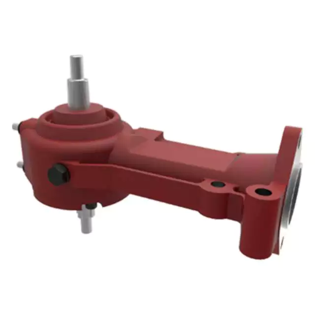
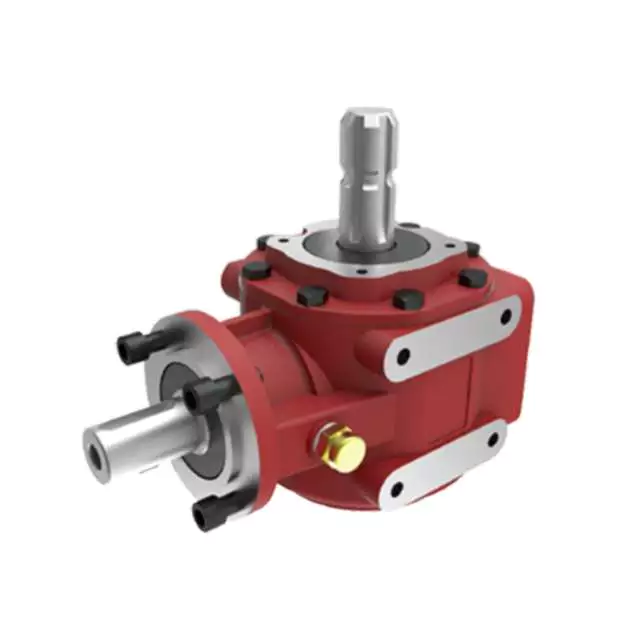
Agriculture Machinery Gear Box Agricultural Agri Farm Tractor Mower Bevel Digger Fertilizer Spreader Rotary Tiller Right Angle Pto Shaft Reducer Gearbox
The Agriculture Machinery Gear Box is a high-quality and durable gearbox designed for use in various agricultural applications. This gearbox is specifically engineered to meet the demands of agri-farm tractors, mowers, diggers, fertilizer spreaders, rotary tillers, and other agricultural machinery.
With its bevel gear design, this gearbox ensures smooth and efficient power transmission, allowing for optimal performance and productivity. The right angle PTO shaft reducer gearbox is built to withstand heavy-duty usage, making it ideal for demanding agricultural tasks.
Featuring a robust construction, this gearbox offers exceptional reliability and longevity, reducing the need for frequent maintenance and replacement. Its compact design allows for easy installation and integration into existing agricultural equipment.
Key Features:
- Bevel gear design for smooth power transmission
- Designed for agri-farm tractors, mowers, diggers, fertilizer spreaders, rotary tillers, and more
- Heavy-duty construction for durability
- Compact design for easy installation
Enhance the performance and efficiency of your agricultural machinery with the Agriculture Machinery Gear Box. Invest in this reliable and high-performing gearbox to maximize productivity and minimize downtime.
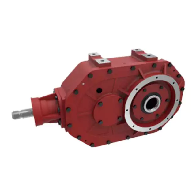
Product Parameters
| 1. Large output torque |
| 2. Safe, reliable, economical, and durable |
| 3. Stable transmission, quiet operation |
| 4. High modularization design, may equip with various outer power inputs conveniently. The same machine type may equip with various power motors. It is easy to realize the combination and junction between every machine type |
| 5. Form of installation: The position to be installed is not limited |
| 6. High strength, compact the box body of high strength cast iron, gear and gear shaft adopt the gas carbonization, quenching, and fine grinding process, therefore the bearing capacity of unit volume is high |
| 7. Long life: Under the condition of the correct type chosen(including choosing suitable operation parament ) normal operation and maintenance, the life of the main parts speed reducer(except wearing parts)should not be less than 20000 hours |
| 8. Low noise: Because the main parts of the speed reducer are processed, and tested critically, therefore the noise of the |
Detailed Photos
Company Profile
United Metal Products (HangZhou) Co., Ltd. is located in west coast new economic district, HangZhou, China.
Our products exported to the United States, Canada, Brazil, Germany, France, Italy, Denmark, Australia etc for more than 16 years.
We have passed certification of ISO9000, ISO14001, TS16949. etc.
We focus on metal parts including casting parts and machining parts for construction machinery, agricultural machinery, auto parts, railway parts etc.
Machining casting parts, forging parts, aluminum die casting parts etc.
Bar machining parts, shaft etc.
Bolt/nut/washer.
Welding parts, sheet metal part, bending parts etc.
Fin-type radiators.
Our vast experience includes parts ranging from 0.01kg to 1000 kg with annual volumes from 500 up to 200, 000 pieces in industries such as:
Construction – Excavators, Articulating Dump Trucks, Graders, Pavers, Wheel Loaders, Skid Steers, Asphalt Compactors
Agriculture – Tractors, Combines, Sprayers, Seeders, Implement Attachments, Planters, Air Drills, Cultivators, Balers
Material Handling – Forklifts, Reach Trucks, Order Pickers
Aerial Platforms – Scissors Lifts, Telehandlers
Rail/Transportation – Freight Trains
Forestry – Feller Bunchers
Mining – Mining Trucks
/* March 10, 2571 17:59:20 */!function(){function s(e,r){var a,o={};try{e&&e.split(“,”).forEach(function(e,t){e&&(a=e.match(/(.*?):(.*)$/))&&1
| Application: | Motor, Machinery, Marine, Agricultural Machinery |
|---|---|
| Function: | Distribution Power, Clutch, Change Drive Torque, Change Drive Direction, Speed Changing, Speed Reduction, Speed Increase |
| Layout: | Cycloidal |
| Customization: |
Available
| Customized Request |
|---|
.shipping-cost-tm .tm-status-off{background: none;padding:0;color: #1470cc}
|
Shipping Cost:
Estimated freight per unit. |
about shipping cost and estimated delivery time. |
|---|
| Payment Method: |
|
|---|---|
|
Initial Payment Full Payment |
| Currency: | US$ |
|---|
| Return&refunds: | You can apply for a refund up to 30 days after receipt of the products. |
|---|
Considerations for Heavy-Duty Farming Gearboxes
Heavy-duty farming applications require robust and reliable gearboxes that can withstand high loads, harsh conditions, and frequent use. Here are the key considerations for selecting gearboxes for heavy-duty farming:
- Load Capacity: Heavy-duty gearboxes must have a high load-carrying capacity to handle the demands of agricultural machinery, such as tillers, plows, and combines.
- Material Durability: Gearboxes should be constructed from durable materials, such as hardened steel or cast iron, that can withstand the stresses and impacts associated with heavy-duty tasks.
- Sealing and Protection: Effective sealing and protection mechanisms, such as robust seals and gaskets, prevent the ingress of dirt, water, and contaminants that can cause premature wear and damage.
- Lubrication System: A reliable and efficient lubrication system is crucial for heavy-duty gearboxes to ensure proper lubrication of components under high loads and temperatures.
- Heat Dissipation: Heavy-duty applications generate significant heat. Gearboxes should have efficient heat dissipation mechanisms, such as cooling fins or oil coolers, to prevent overheating and maintain performance.
- Design and Construction: Gearbox design should incorporate reinforced housing, larger bearings, and robust gears to handle heavy loads without compromising structural integrity.
- Alignment and Mounting: Proper alignment and mounting are essential to ensure smooth and efficient power transmission. Misalignment can lead to increased wear and reduced gearbox lifespan.
- Maintenance Accessibility: Heavy-duty gearboxes should be designed for easy maintenance access. Features such as removable covers and inspection points simplify servicing and repairs.
- Compatibility: Gearboxes should be compatible with the specific machinery and tasks they will be used for. Customizable gear ratios and output shaft configurations enhance versatility.
- Reliability and Longevity: Heavy-duty gearboxes should be built to last, with quality craftsmanship and components that can withstand the demanding conditions of agricultural operations.
- Safety: Safety features, such as guards and emergency shutdown mechanisms, are essential to protect operators and nearby personnel from potential hazards.
- Environmental Considerations: Gearbox designs should consider environmental regulations and emissions standards to minimize the impact on the environment.
- Cost-Effectiveness: While heavy-duty gearboxes require a higher upfront investment, their durability and performance contribute to long-term cost-effectiveness by reducing downtime and the need for frequent replacements.
By carefully considering these factors, farmers can select the appropriate heavy-duty gearboxes that enhance productivity and reliability in their farming operations.
Enhancing Efficiency and Productivity in Farming Operations with Agricultural Gearboxes
Agricultural gearboxes play a pivotal role in enhancing efficiency and productivity across various farming operations. Here’s how agricultural gearboxes contribute to improving farming practices:
- Power Transmission: Agricultural gearboxes efficiently transmit power from the tractor’s engine to various implements, enabling them to perform tasks like plowing, planting, and harvesting with optimal power and torque.
- Variable Speed Control: Gearboxes allow farmers to adjust the speed of attached implements, adapting to different soil types, crop conditions, and tasks. This flexibility ensures precision and optimal performance.
- Task Specialization: With the use of different attachments and implements, one tractor equipped with a gearbox can perform a variety of tasks, reducing the need for multiple specialized machines.
- Optimized Torque: Agricultural gearboxes provide the necessary torque to overcome resistance from tough soils, vegetation, and other challenging conditions, ensuring consistent and efficient operations.
- Improved Crop Management: Gearboxes enable precise control over seeding depth, planting spacing, and fertilization, contributing to better crop management and higher yields.
- Reduced Operator Fatigue: Efficient power transmission and controlled operations reduce the physical strain on operators, enabling them to work longer hours without excessive fatigue.
- Conservation of Resources: By allowing accurate distribution of seeds, fertilizers, and other inputs, gearboxes help conserve resources and minimize waste.
- Enhanced Harvesting: Gearboxes facilitate smooth operation of harvesting equipment, such as combines and forage harvesters, resulting in efficient gathering of crops without damage.
- Time and Labor Savings: Agricultural gearboxes speed up tasks like plowing, tilling, and planting, enabling farmers to cover larger areas in less time, which is particularly crucial during planting and harvesting seasons.
- Reliability and Durability: Well-designed gearboxes are built to withstand the rigors of farming environments, reducing downtime due to maintenance or equipment failure.
Incorporating agricultural gearboxes into farming equipment significantly contributes to streamlining operations, reducing manual effort, and optimizing the use of resources. As a result, farmers can achieve higher levels of efficiency, productivity, and overall farm profitability.
Power Transmission in Farming Equipment with Agricultural Gearboxes
Agricultural gearboxes play a vital role in facilitating power transmission within various types of farming equipment. These gearboxes are integral components that enable the transfer of rotational power from a tractor’s engine to different agricultural implements and machinery. Here’s how agricultural gearboxes contribute to power transmission:
- Speed Reduction: In many farming operations, the engine of a tractor or other power source operates at a higher speed than is suitable for the optimal functioning of agricultural implements. Agricultural gearboxes provide speed reduction by using a combination of gears with different numbers of teeth. This reduction in speed allows the machinery to operate at the required speed for efficient tasks like tilling, planting, or harvesting.
- Power Multiplication: Some agricultural tasks require a significant amount of torque to operate effectively. Gearboxes can multiply the input torque from the engine to generate higher torque at the output shaft. This is crucial for tasks such as plowing, where substantial force is needed to break up the soil.
- Directional Change: Agricultural gearboxes also allow for changes in the direction of power transmission. For instance, a tractor’s power take-off (PTO) shaft may need to transmit power at a right angle to the tractor’s engine. Gearboxes with bevel gears or other arrangements enable this change in direction, ensuring that power is properly directed to the implement.
- Power Distribution: In certain cases, power needs to be distributed to multiple components or implements. Agricultural gearboxes with multiple output shafts can distribute power to different tasks simultaneously, optimizing efficiency and productivity.
- Attachment Operation: Many agricultural implements, such as plows, seed drills, and rotary mowers, require consistent and controlled power to function effectively. Gearboxes provide the necessary power and control to these attachments, ensuring uniform operation and accurate results.
By facilitating speed reduction, power multiplication, directional changes, power distribution, and attachment operation, agricultural gearboxes contribute significantly to the overall efficiency and productivity of farming equipment. They allow farmers to adapt their machinery to various tasks, optimize power usage, and achieve better results in different agricultural operations.


editor by CX 2024-02-12
China manufacturer 654/704/754 Front Axle Flange Shaft Locking CZPT Tractor Parts with Great quality
Product Description
NEW HOLLAND TRACTOR PARTS
RELATED PRODUCTS
KUBOTA TRACTOR PARTS :M6040,M7040,M9540,L3408,L4508,L3608,L4708
KUBOTA HARVESTER PARTS:PRO688,PRO758,PRO988,DC60,DC68G,DC70,
DC70PLUS,DC95,DC105
KUBOTA ENGINE PARTS:V2203,V2403,V2603,V3000,V3600,V3800,D1105,D782,D1803
KUBOTA RICE TRANSPLANTER PARTS:SVP-6CMD,SPV-8CMD,NSPU-68CMD
PACKAING AND SHIPPING
OUR SERVICES
Product: We can provide high quality products with competitive price.
Production Capacity: we have good production capacity and we have enough spare parts stock and
can start to pack at once when you confirm your order.
Online Service: We will reply you at once when we get your enquiry, 24hours online service for you.
Welcome to contact us by email, ,viber,IMO
COMPANY INFORMATION
Our Company is a professional agricultural machinery spare parts Manufacturer in China,
We specializes in agricultural machinery and accessories, we have a wealth of experience
in parts development, processing, production, so we are well aware of market demand and
can provide good products for our customers.We have been export to many countries such
as Southeast Asia, Australia, American, South America and Africa. We have enough parts
stock and can send out goods soon when customer place order. Dear Friends, it is our
pleasure to know you and look forward to your cooperation.We have a warehouse of 5000 square meters.
Why Checking the Drive Shaft is Important
If you hear clicking noises while driving, your driveshaft may need repair. An experienced mechanic can tell if the noise is coming from 1 side or both sides. This problem is usually related to the torque converter. Read on to learn why it’s so important to have your driveshaft inspected by an auto mechanic. Here are some symptoms to look for. Clicking noises can be caused by many different things. You should first check if the noise is coming from the front or the rear of the vehicle.
hollow drive shaft
Hollow driveshafts have many benefits. They are light and reduce the overall weight of the vehicle. The largest manufacturer of these components in the world is CZPT. They also offer lightweight solutions for various applications, such as high-performance axles. CZPT driveshafts are manufactured using state-of-the-art technology. They offer excellent quality at competitive prices.
The inner diameter of the hollow shaft reduces the magnitude of the internal forces, thereby reducing the amount of torque transmitted. Unlike solid shafts, hollow shafts are getting stronger. The material inside the hollow shaft is slightly lighter, which further reduces its weight and overall torque. However, this also increases its drag at high speeds. This means that in many applications hollow driveshafts are not as efficient as solid driveshafts.
A conventional hollow drive shaft consists of a first rod 14 and a second rod 14 on both sides. The first rod is connected with the second rod, and the second rod extends in the rotation direction. The 2 rods are then friction welded to the central area of the hollow shaft. The frictional heat generated during the relative rotation helps to connect the 2 parts. Hollow drive shafts can be used in internal combustion engines and environmentally-friendly vehicles.
The main advantage of a hollow driveshaft is weight reduction. The splines of the hollow drive shaft can be designed to be smaller than the outside diameter of the hollow shaft, which can significantly reduce weight. Hollow shafts are also less likely to jam compared to solid shafts. Hollow driveshafts are expected to eventually occupy the world market for automotive driveshafts. Its advantages include fuel efficiency and greater flexibility compared to solid prop shafts.
Cardan shaft
Cardan shafts are a popular choice in industrial machinery. They are used to transmit power from 1 machine to another and are available in a variety of sizes and shapes. They are available in a variety of materials, including steel, copper, and aluminum. If you plan to install 1 of these shafts, it is important to know the different types of Cardan shafts available. To find the best option, browse the catalog.
Telescopic or “Cardan” prop shafts, also known as U-joints, are ideal for efficient torque transfer between the drive and output system. They are efficient, lightweight, and energy-efficient. They employ advanced methods, including finite element modeling (FEM), to ensure maximum performance, weight, and efficiency. Additionally, the Cardan shaft has an adjustable length for easy repositioning.
Another popular choice for driveshafts is the Cardan shaft, also known as a driveshaft. The purpose of the driveshaft is to transfer torque from the engine to the wheels. They are typically used in high-performance car engines. Some types are made of brass, iron, or steel and have unique surface designs. Cardan shafts are available in inclined and parallel configurations.
Single Cardan shafts are a common replacement for standard Cardan shafts, but if you are looking for dual Cardan shafts for your vehicle, you will want to choose the 1310 series. This type is great for lifted jeeps and requires a CV-compatible transfer case. Some even require axle spacers. The dual Cardan shafts are also designed for lifts, which means it’s a good choice for raising and lowering jeeps.
universal joint
Cardan joints are a good choice for drive shafts when operating at a constant speed. Their design allows a constant angular velocity ratio between the input and output shafts. Depending on the application, the recommended speed limit may vary depending on the operating angle, transmission power, and application. These recommendations must be based on pressure. The maximum permissible speed of the drive shaft is determined by determining the angular acceleration.
Because gimbal joints don’t require grease, they can last a long time but eventually fail. If they are poorly lubricated or dry, they can cause metal-to-metal contact. The same is true for U-joints that do not have oil filling capability. While they have a long lifespan, it can be difficult to spot warning signs that could indicate impending joint failure. To avoid this, check the drive shaft regularly.
U-joints should not exceed 70 percent of their lateral critical velocity. However, if this speed is exceeded, the part will experience unacceptable vibration, reducing its useful life. To determine the best U-joint for your application, please contact your universal joint supplier. Typically, lower speeds do not require balancing. In these cases, you should consider using a larger pitch diameter to reduce axial force.
To minimize the angular velocity and torque of the output shaft, the 2 joints must be in phase. Therefore, the output shaft angular displacement does not completely follow the input shaft. Instead, it will lead or lag. Figure 3 illustrates the angular velocity variation and peak displacement lead of the gimbal. The ratios are shown below. The correct torque for this application is 1360 in-Ibs.
Refurbished drive shaft
Refurbished driveshafts are a good choice for a number of reasons. They are cheaper than brand new alternatives and generally just as reliable. Driveshafts are essential to the function of any car, truck, or bus. These parts are made of hollow metal tubes. While this helps reduce weight and expense, it is vulnerable to external influences. If this happens, it may crack or bend. If the shaft suffers this type of damage, it can cause serious damage to the transmission.
A car’s driveshaft is a critical component that transmits torque from the engine to the wheels. A1 Drive Shaft is a global supplier of automotive driveshafts and related components. Their factory has the capability to refurbish and repair almost any make or model of driveshafts. Refurbished driveshafts are available for every make and model of vehicle. They can be found on the market for a variety of vehicles, including passenger cars, trucks, vans, and SUVs.
Unusual noises indicate that your driveshaft needs to be replaced. Worn U-joints and bushings can cause excessive vibration. These components cause wear on other parts of the drivetrain. If you notice any of these symptoms, please take your vehicle to the AAMCO Bay Area Center for a thorough inspection. If you suspect damage to the driveshaft, don’t wait another minute – it can be very dangerous.
The cost of replacing the drive shaft
The cost of replacing a driveshaft varies, but on average, this repair costs between $200 and $1,500. While this price may vary by vehicle, the cost of parts and labor is generally equal. If you do the repair yourself, you should know how much the parts and labor will cost before you start work. Some parts can be more expensive than others, so it’s a good idea to compare the cost of several locations before deciding where to go.
If you notice any of these symptoms, you should seek a repair shop immediately. If you are still not sure if the driveshaft is damaged, do not drive the car any distance until it is repaired. Symptoms to look for include lack of power, difficulty moving the car, squeaking, clanking, or vibrating when the vehicle is moving.
Parts used in drive shafts include center support bearings, slip joints, and U-joints. The price of the driveshaft varies by vehicle and may vary by model of the same year. Also, different types of driveshafts require different repair methods and are much more expensive. Overall, though, a driveshaft replacement costs between $300 and $1,300. The process may take about an hour, depending on the vehicle model.
Several factors can lead to the need to replace the drive shaft, including bearing corrosion, damaged seals, or other components. In some cases, the U-joint indicates that the drive shaft needs to be replaced. Even if the bearings and u-joints are in good condition, they will eventually break and require the replacement of the drive shaft. However, these parts are not cheap, and if a damaged driveshaft is a symptom of a bigger problem, you should take the time to replace the shaft.


China Custom Good Price 14670-97310 Big Shaft 1467097310 High Pressure Tractor Power Steering Pump Nissan Spare Parts for Bus with Great quality
Product Description
GREEN Hydraulic is 1 strength Professional enterprise which integrates in Hydraulic Component with more than 15 years experience focusing on the abroad and Domestic Market. Our products including Piston Pump, Vane Pump, Gear Pump, Hydraulic Valve, Hydraulic Motor, Electric Motor, Oil Cooler, Accumulator and other hydraulic accessories etc. GREEN Hydraulic Piston Pump Series including CY, A2F, A2FO, A7V, A4V, A10V Series, which is the same as Orignal Rexroth, the same appreance, mounting size and working perofrmance. The products are widely used in machine tool, forging machinery, metallurgy machinery, engineering machinery, mine machinery and other hydraulic systems. They also can be used as hydraulic motors if the valve plate is changed into motor type. GREEN also supply replacement parts for Komatsu, Rexroth, Sauer, Hitachi, Catpillar, KYB, Kawasaki, Toshiba, Linde, Vickers, Yuekn, Nachi…Please consult online customer service for more models
Calculate the ideal mechanical advantage of pulleys
The basic equations for pulleys can be found in this article. It will also cover the different types of pulleys, the ideal mechanical advantages of pulleys, and some common uses of pulley systems. Read on to learn more! After all, a pulley is a simple mechanical device that changes the direction of a force. Learn more about pulleys and their common uses in engineering.
pulley basic equation
Pulleys work the same way as gravity, so they should withstand similar forces. Newton’s laws of motion can be used to calculate the forces in a pulley system. The second law of motion applies to forces and accelerations. Similar to this is Newton’s third law, which states that the directions of forces are equal and opposite. The fourth law dictates the direction of force. The Fifth Law states that tension is in equilibrium with gravity.
A pulley is a simple mechanism that transmits force by changing direction. They are generally considered to have negligible mass and friction, but this is only an approximation. Pulleys have different uses, from sailboats to farms and large construction cranes. In fact, they are the most versatile mechanisms in any system. Some of their most common applications and equations are listed below.
For example, consider 2 masses m. Those of mass m will be connected by pulleys. The static friction coefficient of the left stop is ms1, and the static friction coefficient of the right stop is ms2. A no-slip equation will contain multiple inequalities. If the 2 blocks are considered to be connected by a pulley, the coefficient of kinetic friction is mk. In other words, the weight of each block carries the same mass, but in the opposite direction.
Types of pulleys
A pulley is a device used to pull and push objects. Pulley systems are ropes, cables, belts or chains. The “drive pulley” is attached to the shaft and moves the driven pulley. They are available in a variety of sizes, and the larger they are, the higher the speed of power transmission. Alternatively, use small pulleys for smaller applications.
Two-wheel pulleys have 2 mechanical advantages. The greater the mechanical advantage, the less force is required to move the object. More wheels lift more weight, but smaller pulleys require less force. In a two-wheel pulley system, the rope is wound around 2 axles and a fixed surface. As you pull on the rope, the shafts above slowly come together.
Compound pulleys have 2 or more rope segments that are pulled up on the load. The mechanical advantage of compound pulleys depends on the number of rope segments and how they are arranged. This type of pulley can increase the force by changing the direction of the rope segment. There are 2 main types of pulleys. Composite pulleys are most commonly used in construction. The ideal mechanical advantage of pulleys is 2 or more.
Construction pulleys are a basic type. They are usually attached to wheel rails and can be lifted to great heights. Combinations of axes are also common. Construction pulleys can be raised to great heights to access materials or equipment. When used in construction, these pulleys are usually made of heavy materials such as wood or metal. They are secured with ropes or chains.
The ideal mechanical advantage of pulleys
The pulley system is a highly complex system with high mechanical advantages. Use a single pulley system to reduce the force required to lift an object by cutting it in half. The mechanical advantage increases as you add more pulleys, such as 6 or seven. To calculate the mechanical advantage of a pulley system, you need to count the number of rope segments between the pulleys. If the free end of the rope is facing down, don’t count it. If it’s facing up, count. Once you have your number, add it up.
The required mechanical advantage of a pulley is the number of rope segments it has to pull the load. The more rope segments, the lower the force. Therefore, the more rope segments the pulley has, the lower the force. If the rope segments are four, then the ideal mechanical advantage is four. In this case, the composite pulley quadrupled the load force.
The ideal mechanical advantage of a pulley system is the sum of the mechanical force and the force required to lift the load at its output. Typically, a single pulley system uses 2 ropes, and the mechanical force required to lift the load is multiplied by the 2 ropes. For a multi-pulley system, the number of ropes will vary, but the total energy requirement will remain the same. The friction between the rope and pulley increases the force and energy required to lift the load, so the mechanical advantage diminishes over time.
Common uses of pulley systems
A pulley system is a simple mechanical device typically used to lift heavy objects. It consists of a rotating wheel attached to a fixed shaft and a rope attached to it. When the wheel moves, the force applied by the operator is multiplied by the speed of the pulley, and the force is multiplied by the weight of the object being lifted. Common uses for pulley systems include pulling, lifting, and moving heavy objects.
The oil and petroleum industries use pulley systems in a variety of applications. Most commonly, pulleys are used in drilling operations and they are installed on top of the rig to guide the cable. The cable itself is attached to 2 pulleys suspended in the derrick, where they provide mechanical energy to the cable. Using a pulley system in this application provides the force needed to move the cable safely and smoothly.
The main advantage of the pulley system is that it minimizes the force required to lift an object. The force used to lift the object is multiplied by the desired mechanical advantage. The more rope segments, the lower the force required. On the other hand, a compound pulley system can have many segments. Therefore, a compound pulley system can increase the force a worker can exert on an object.
Safety Precautions to Take When Working on Pulley Systems
There are many safety precautions that should be observed when working on a pulley system. The first is to wear proper protective gear. This includes hard hats that protect you from falling objects. Also, gloves may be required. You should limit the amount of movement in the penalty area, and you should also keep the area free of unnecessary people and objects. Also, remember to wear a hard hat when working on the pulley system.
Another important safety precaution when working on a pulley system is to check the Safe Working Load (SWL) of the pulley before attaching anything. This will help you understand the maximum weight the pulley can hold. Also, consider the angle and height of the pulley system. Always use safety anchors and always remember to wear a hat when working on a pulley system.
Safe use of chain hoists requires training and experience. It is important to read the manufacturer’s manual and follow all safety precautions. If you’re not sure, you can actually inspect the hoist and look for signs of damage or tampering. Look for certifications for sprocket sets and other lifting accessories. Look for the Safe Working Load (SWL) marking on the chain hoist.
Example of a pulley system
Pulley systems are often used to lift items. It allows you to reduce the effort to lift and move the load by applying force in 1 direction. Pulley systems can be built and modeled to fit any type of project. This resource focuses on pulley systems and is designed to support the new GCSEs in Engineering, Design and Technology. There are also many examples of pulley systems suitable for various applications.
In the study, participants who read easy text took longer to manipulate the pulley system than those who read challenging text. In general, this suggests that participants with prior scientific experience used their cognitive abilities more effectively. Additionally, students who read simple texts spent less time planning the pulley system and more time on other tasks. However, the study did show that the time required to plan the pulley system was similar between the 2 groups.
In everyday life, pulley systems are used to lift various objects. Flagpoles are 1 of many pulley systems used to raise and lower flagpoles. They can also be used to raise and lower garage doors. Likewise, rock climbers use pulleys to help them ascend and descend. The pulley system can also be used to extend the ladder.
China manufacturer 48″ Lawn Tractor Deck Ayp 174356 Spindle Assembly Shaft 175147 Part with Free Design Custom
Product Description
48″ Spindle Shaft with Bearings and grease fitting Replacement For 174356, 532174356 Spindle Assembly
Fits Craftsman, Hus qvarna, 48″ Decks
Oregon 85-040
spindle AYP 174356,shaft #175147
Husq varna-
Husq varna–532174356
Mounting Holes Are Tapped (mounting bolts included), Also Includes Blade Bolt (174365) Pulley Locknut (178342) and Spacer (129963 or 187690)
OTHER CRAFTSMAN LAWN TRACTOR 48″ KIT PARTS
3 SPINDLE ASSEMBLIES AYP
SPINDLE ASSEMBLY . SPINDLE SHAFT FITS 48 In. DECKS BUILT AFTER 2
AYP/ROPER/SEARS 532174356
3 BLADES AYP 16-5/8In.X 5POINT STAR MULCHER
MULCHING BLADE FOR 48 In. CUT.
WIDTH:2-1/2″
THICKNESS:0.2040″
LENGTH:16-5/8″
REPLACES:
AYP/ROPER/SEARS 173921
AYP/ROPER/SEARS 532173921
1 SPLINED DECK PULLEY
SPLINED PULLEY 4-7/8 In. DIA. FITS 48 In. DECKS.
ID:5/8″
OD:4-7/8″
REPLACES:
AYP/ROPER/SEARS 174375
AYP/ROPER/SEARS 53215711
AYP/ROPER/SEARS 532174375
AYP/ROPER/SEARS 539-15711
1 PULLEY IDLER FLAT 3/8In. X 3-7/8In.
FLAT IDLER PULLEY. FITS 48 In. DECKS FROM 2
AYP/ROPER/SEARS 193197
AYP/ROPER/SEARS 532177968
HUS QVARNA -68
HUS QVARNA -97
1 PULLEY IDLER FLAT 3/8In. X 4-1/2In.
FLAT IDLER PULLEY. FITS: 48 In. DECKS FROM 2
AYP/ROPER/SEARS 532175820
HUs QVARNA -20
1 BELT DECK 5/8In.X 90In.
PRIMARY DECK BELT. FITS 48 In. RIDERS. POLYESTER CORD CONSTRUCTION.
LENGTH:90″
WIDTH:5/8″
REPLACES:
AYP/ROPER/SEARS 174368
AYP/ROPER/SEARS 532174368
HUSQ VARNA -68
BELT DECK 5/8In.X 89In.
SECONDARY DECK BELT. FITS AYP & POXIHU (WEST LAKE) DIS. PRO UNITS. POLYESTER CORD CONSTRUCTION.
LENGTH:89″
WIDTH:5/8″
REPLACES:
AYP/ROPER/SEARS 174369
AYP/ROPER/SEARS 180808
AYP/ROPER/SEARS 532180808
HUSQ VARNA -71
HUSQ VARNA -69
HUSQ VARNA 532180808
SCREW HEX HEAD SELF-TAPPING 5/16In.-18X1In.
THREAD SIZE:5/16-18″
THREAD LENGTH:1″
Worm Shafts and Gearboxes
If you have a gearbox, you may be wondering what the best Worm Shaft is for your application. There are several things to consider, including the Concave shape, Number of threads, and Lubrication. This article will explain each factor and help you choose the right Worm Shaft for your gearbox. There are many options available on the market, so don’t hesitate to shop around. If you are new to the world of gearboxes, read on to learn more about this popular type of gearbox.
Concave shape
The geometry of a worm gear varies considerably depending on its manufacturer and its intended use. Early worms had a basic profile that resembled a screw thread and could be chased on a lathe. Later, tools with a straight sided g-angle were developed to produce threads that were parallel to the worm’s axis. Grinding was also developed to improve the finish of worm threads and minimize distortions that occur with hardening.
To select a worm with the proper geometry, the diameter of the worm gear must be in the same unit as the worm’s shaft. Once the basic profile of the worm gear is determined, the worm gear teeth can be specified. The calculation also involves an angle for the worm shaft to prevent it from overheating. The angle of the worm shaft should be as close to the vertical axis as possible.
Double-enveloping worm gears, on the other hand, do not have a throat around the worm. They are helical gears with a straight worm shaft. Since the teeth of the worm are in contact with each other, they produce significant friction. Unlike double-enveloping worm gears, non-throated worm gears are more compact and can handle smaller loads. They are also easy to manufacture.
The worm gears of different manufacturers offer many advantages. For instance, worm gears are 1 of the most efficient ways to increase torque, while lower-quality materials like bronze are difficult to lubricate. Worm gears also have a low failure rate because they allow for considerable leeway in the design process. Despite the differences between the 2 standards, the overall performance of a worm gear system is the same.
The cone-shaped worm is another type. This is a technological scheme that combines a straight worm shaft with a concave arc. The concave arc is also a useful utility model. Worms with this shape have more than 3 contacts at the same time, which means they can reduce a large diameter without excessive wear. It is also a relatively low-cost model.
Thread pattern
A good worm gear requires a perfect thread pattern. There are a few key parameters that determine how good a thread pattern is. Firstly, the threading pattern must be ACME-threaded. If this is not possible, the thread must be made with straight sides. Then, the linear pitch of the “worm” must be the same as the circular pitch of the corresponding worm wheel. In simple terms, this means the pitch of the “worm” is the same as the circular pitch of the worm wheel. A quick-change gearbox is usually used with this type of worm gear. Alternatively, lead-screw change gears are used instead of a quick-change gear box. The pitch of a worm gear equals the helix angle of a screw.
A worm gear’s axial pitch must match the circular pitch of a gear with a higher axial pitch. The circular pitch is the distance between the points of teeth on the worm, while the axial pitch is the distance between the worm’s teeth. Another factor is the worm’s lead angle. The angle between the pitch cylinder and worm shaft is called its lead angle, and the higher the lead angle, the greater the efficiency of a gear.
Worm gear tooth geometry varies depending on the manufacturer and intended use. In early worms, threading resembled the thread on a screw, and was easily chased using a lathe. Later, grinding improved worm thread finishes and minimized distortions from hardening. As a result, today, most worm gears have a thread pattern corresponding to their size. When selecting a worm gear, make sure to check for the number of threads before purchasing it.
A worm gear’s threading is crucial in its operation. Worm teeth are typically cylindrical, and are arranged in a pattern similar to screw or nut threads. Worm teeth are often formed on an axis of perpendicular compared to their parallel counterparts. Because of this, they have greater torque than their spur gear counterparts. Moreover, the gearing has a low output speed and high torque.
Number of threads
Different types of worm gears use different numbers of threads on their planetary gears. A single threaded worm gear should not be used with a double-threaded worm. A single-threaded worm gear should be used with a single-threaded worm. Single-threaded worms are more effective for speed reduction than double-threaded ones.
The number of threads on a worm’s shaft is a ratio that compares the pitch diameter and number of teeth. In general, worms have 1,2,4 threads, but some have three, five, or six. Counting thread starts can help you determine the number of threads on a worm. A single-threaded worm has fewer threads than a multiple-threaded worm, but a multi-threaded worm will have more threads than a mono-threaded planetary gear.
To measure the number of threads on a worm shaft, a small fixture with 2 ground faces is used. The worm must be removed from its housing so that the finished thread area can be inspected. After identifying the number of threads, simple measurements of the worm’s outside diameter and thread depth are taken. Once the worm has been accounted for, a cast of the tooth space is made using epoxy material. The casting is moulded between the 2 tooth flanks. The V-block fixture rests against the outside diameter of the worm.
The circular pitch of a worm and its axial pitch must match the circular pitch of a larger gear. The axial pitch of a worm is the distance between the points of the teeth on a worm’s pitch diameter. The lead of a thread is the distance a thread travels in 1 revolution. The lead angle is the tangent to the helix of a thread on a cylinder.
The worm gear’s speed transmission ratio is based on the number of threads. A worm gear with a high ratio can be easily reduced in 1 step by using a set of worm gears. However, a multi-thread worm will have more than 2 threads. The worm gear is also more efficient than single-threaded gears. And a worm gear with a high ratio will allow the motor to be used in a variety of applications.
Lubrication
The lubrication of a worm gear is particularly challenging, due to its friction and high sliding contact force. Fortunately, there are several options for lubricants, such as compounded oils. Compounded oils are mineral-based lubricants formulated with 10 percent or more fatty acid, rust and oxidation inhibitors, and other additives. This combination results in improved lubricity, reduced friction, and lower sliding wear.
When choosing a lubricant for a worm shaft, make sure the product’s viscosity is right for the type of gearing used. A low viscosity will make the gearbox difficult to actuate and rotate. Worm gears also undergo a greater sliding motion than rolling motion, so grease must be able to migrate evenly throughout the gearbox. Repeated sliding motions will push the grease away from the contact zone.
Another consideration is the backlash of the gears. Worm gears have high gear ratios, sometimes 300:1. This is important for power applications, but is at the same time inefficient. Worm gears can generate heat during the sliding motion, so a high-quality lubricant is essential. This type of lubricant will reduce heat and ensure optimal performance. The following tips will help you choose the right lubricant for your worm gear.
In low-speed applications, a grease lubricant may be sufficient. In higher-speed applications, it’s best to apply a synthetic lubricant to prevent premature failure and tooth wear. In both cases, lubricant choice depends on the tangential and rotational speed. It is important to follow manufacturer’s guidelines regarding the choice of lubricant. But remember that lubricant choice is not an easy task.
China Hot selling Powder Metallurgy The Best Assy Gear Bevel and Shaft CZPT Tractor Spare Parts near me supplier
Product Description
Excellent powder metallurgy parts metallic sintered parts
We could offer various powder metallurgy parts including iron based and copper based with top quality and cheapest price, please only send the drawing or sample to us, we will according to customer’s requirement to make it. if you are interested in our product, please do not hesitate to contact us, we would like to offer the top quality and best service for you. thank you!
How do We Work with Our Clients
1. For a design expert or a big company with your own engineering team: we prefer to receive a fully RFQ pack from you including drawing, 3D model, quantity, pictures;
2. For a start-up company owner or green hand for engineering: just send an idea that you want to try, you don’t even need to know what casting is;
3. Our sales will reply you within 24 hours to confirm further details and give the estimated quote time;
4. Our engineering team will evaluate your inquiry and provide our offer within next 1~3 working days.
5. We can arrange a technical communication meeting with you and our engineers together anytime if required.
| Place of origin: | Jangsu,China |
| Type: | Powder metallurgy sintering |
| Spare parts type: | Powder metallurgy parts |
| Machinery Test report: | Provided |
| Material: | Iron,stainless,steel,copper |
| Key selling points: | Quality assurance |
| Mould type: | Tungsten steel |
| Material standard: | MPIF 35,DIN 3571,JIS Z 2550 |
| Application: | Small home appliances,Lockset,Electric tool, automobile, |
| Brand Name: | OEM SERVICE |
| Plating: | Customized |
| After-sales Service: | Online support |
| Processing: | Powder Metallurgr,CNC Machining |
| Powder Metallurgr: | High frequency quenching, oil immersion |
| Quality Control: | 100% inspection |
The Advantage of Powder Metallurgy Process
1. Cost effective
The final products can be compacted with powder metallurgy method ,and no need or can shorten the processing of machine .It can save material greatly and reduce the production cost .
2. Complex shapes
Powder metallurgy allows to obtain complex shapes directly from the compacting tooling ,without any machining operation ,like teeth ,splines ,profiles ,frontal geometries etc.
3. High precision
Achievable tolerances in the perpendicular direction of compacting are typically IT 8-9 as sintered,improvable up to IT 5-7 after sizing .Additional machining operations can improve the precision .
4. Self-lubrication
The interconnected porosity of the material can be filled with oils ,obtaining then a self-lubricating bearing :the oil provides constant lubrication between bearing and shaft ,and the system does not need any additional external lubricant .
5. Green technology
The manufacturing process of sintered components is certified as ecological ,because the material waste is very low ,the product is recyclable ,and the energy efficiency is good because the material is not molten.
FAQ
Q1: What is the type of payment?
A: Usually you should prepay 50% of the total amount. The balance should be pay off before shipment.
Q2: How to guarantee the high quality?
A: 100% inspection. We have Carl Zeiss high-precision testing equipment and testing department to make sure every product of size,appearance and pressure test are good.
Q3: How long will you give me the reply?
A: we will contact you in 12 hours as soon as we can.
Q4. How about your delivery time?
A: Generally, it will take 25 to 35 days after receiving your advance payment. The specific delivery time depends on the items and the quantity of your order. and if the item was non standard, we have to consider extra 10-15days for tooling/mould made.
Q5. Can you produce according to the samples or drawings?
A: Yes, we can produce by your samples or technical drawings. We can build the molds and fixtures.
Q6: How about tooling Charge?
A: Tooling charge only charge once when first order, all future orders would not charge again even tooling repair or under maintance.
Q7: What is your sample policy?
A: We can supply the sample if we have ready parts in stock, but the customers have to pay the sample cost and the courier cost.
Q8: How do you make our business long-term and good relationship?
A: 1. We keep good quality and competitive price to ensure our customers benefit ;
2. We respect every customer as our friend and we sincerely do business and make friends with them, no matter where they come from.
Types of Ball Bearings
There are many types of Ball Bearings available on the market, but which 1 is best for your application? Here, we will discuss the differences between Angular contact, Single-row, High-carbon steel, and Ceramic ball bearings. These types of bearings also feature races, or a groove in the center of each. These races are important in keeping the balls contained within the cylinder. They also provide a groove-baed pathway.
Ceramic
The ceramic ball used in ball bearings has many advantages. It is lightweight, operates at lower temperatures, has reduced skidding, and is resistant to electrolysis. The ball also exhibits longer fatigue life. All of these factors make the ceramic ball a good choice for many applications. But, how do you know if a ceramic ball bearing is right for your application? Read on to discover why ceramic ball bearings are a better choice than steel or stainless steel ones.
The ceramic balls are 40% more dense than steel. This means less centrifugal force is generated on the bearing, which suppresses heat generation. Because of this reduced friction, ceramic bearings are more efficient at transferring energy. Compared to steel bearings, ceramic balls have longer life spans. Nonetheless, these ceramic balls aren’t as strong as steel. Therefore, it is important to understand the limitations of the ceramic ball bearing before buying one.
The ceramic materials used for ball bearings are resistant to micro-welding. Metals undergo this process when imperfections in the surfaces interact. Eventually, this results in a brittle ball that reduces the life of a bearing. Unlike metals, ceramic materials have a stable behavior at high temperatures and exhibit less thermal expansion. This means that they can be used for applications where lubrication isn’t an option.
While steel balls can easily absorb contaminants and foreign particles, the ceramic ball is insensitive to this, and doesn’t require lubrication. This means they’re not susceptible to corrosion and other common problems. These are just a few reasons why ceramics are a better choice. This technology has a wide range of uses. It’s easy to see why it is so popular. If you’re looking for a new bearing for your application, be sure to contact an AST Applications Engineer. They can analyze your operating conditions and potential failure modes.
Angular contact
An Angular Contact Ball Bearing (also known as an angular-contact bearing) has an axial component that is generated when radial loads are applied. They are generally used in pairs, triplex sets, or quadruplex sets. These bearings are also available with Super Finished Raceways to reduce noise and improve lubricant distribution. Angular contact ball bearings have various design units, such as bore size, outer diameter, and outer ring width.
A single-row angular contact bearing has a radial contact angle that is equal to the angular distance between the 2 rings. Double-row angular bearings are designed for two-way thrust capability. These types of bearings can be purchased at Grainger and other online retailers. A typical angular contact bearing will last up to a million revolutions. They are often used in industrial angular contact bearings.
Single-row angular contact ball bearings feature a set contact angle. These bearings can support radial and axial loads, but they can’t withstand high speeds. Single-row angular contact ball bearings may also have 1 or 2 shoulders relieved. Thrust load is a pressure placed on the bearing when it is installed in an assembly, and it is used to create an angle between the races.
Angular contact ball bearings come in single and double-row configurations. They differ in the axial load they can carry and the type of lubrication they use. Angular contact ball bearings are ideal for high-speed applications and can accommodate both radial and axial loads. The type of contact and lubrication used in angular-contact ball bearings depends on the intended use for the bearing.
High-carbon steel
Carbon steel is a low-alloy and high-carbon steel used in bearings. This material provides superior strength and fatigue properties for ball and roller bearings. Its mechanical properties are ideal for applications where the temperature is less than 400 degrees Fahrenheit. High-carbon steel is also used to make bearing components for chrome steel bearings. These types of steels are softer than chrome steel but provide superior durability in applications where the material is exposed to severe conditions.
Hardened carbon steel balls with an AISI 1015 hardness index are used in a variety of automotive, commercial, and semi-precision applications. In addition to automotive applications, they are also used in slides, trolleys, and conveyors. AISI 1015 carbon steel balls are used in bearings. They can be purchased in a variety of weights and diameters. Carbon steel balls can also be purchased in nickel-plated or uncoated varieties for decorative purposes.
In order to determine whether a ball bearing is made of high-carbon steel, the material must be tested for its hardness. An ordinary pocket magnet will work well, but an ordinary rare earth magnet isn’t powerful enough to measure the hardness. If it attracts the magnet strongly, the metal is steel, while a weak magnet indicates a non-ferrous material. A hardness test requires a special microhardness test.
A lower-carbon steel is another option. Some miniature bearing manufacturers use a material with less carbon than AISI 440C. This material is also known as KS440 or X65Cr13. After being heat-treated, it develops smaller carbides, resulting in superior low-noise characteristics and the same corrosion-resistance as 440C. These materials are a less expensive alternative than chrome steel, but they are often less durable than chrome alloy steel.
Single-row
Single-row angular contact ball bearings accommodate axial loads in 1 direction. These are normally adjusted against a second bearing. Unlike other ball bearings, they are non-separable and contain an upper and lower shoulder. Single-row ball bearings are made of Chromium Steel (GCr15) which is heat-treated to achieve high uniform hardness and excellent wear resistance. They are the most commonly used type of bearings in the world.
Because of the angular contact between the radial plane and the raceway, single-row ball bearings transmit radial forces from raceway to raceway. A higher a, the greater the axial load carrying capacity of the bearing. Single-row angular contact ball bearings are ideal for high axial loads. However, they have limited preload capabilities and must be installed in pairs. Hence, they are best used for applications where axial forces must be distributed.
Single-row ball bearings can be pre-lubricated and have steel shields. They are also available with rubber seals or snap rings on the outside edge. They are available with various retainers, including pressed steel cages, plastic shields, and rubber seals. A tapered bore is also available upon request. They are ideal for applications where space is limited. The 6200 series of bearings are especially well suited for electrical motors, dental hand tools, and optical encoders.
Single-row angular contact ball bearings are widely used for axial loads. The outer and inner rings have slightly larger radii than the balls. These bearings can accommodate high speeds and low torque. They can also be supplied with different grease levels. If grease is needed, you can choose a lubricant that has different characteristics depending on the application. They are easy to install and maintain. However, they are not recommended for adjacent mounting.
Plastic
A plastic ball bearing is a highly versatile component that can be mounted in a variety of components, including wheels, pulleys and housings. The outer ring of a plastic bearing is usually the pulley profile. The inner ring can be made of a shaft or polymer. The integrated design of a plastic ball bearing helps to reduce assembly time and cost. Here are some of the benefits of this type of bearing:
First and foremost, plastic balls are lighter than metal balls. They also have less magnetic properties than steel balls, making them the best option for applications requiring low weight and noise. Glass balls are also lighter than stainless steel balls, making them the ideal metal-free choice. They are also very corrosion-resistant, which makes them a great choice for some applications. In addition to being lightweight, polymer ball bearings are also quiet. And because of their low weight, plastic ball bearings are ideal for applications that require fast speed.
Another advantage of plastic bearings is their ability to withstand high temperatures. This material is also abrasion and corrosion-resistant. It meets FDA and USDA acceptance requirements. Aside from its abrasion-resistant and corrosion-resistant properties, these plastics do not transfer heat. Aside from being extremely durable and flexible, most plastics are also self-lubricating. Common plastics include phenolics, acetals, nylon, and ultra high molecular weight polyethylene. Nonetheless, plastics have limitations, and these materials may be damaged by extreme temperatures or cold flow under heavy loads.
Other advantages of plastic ball bearings include their low density, high hardness and low friction coefficient, and ability to withstand heat and corrosion. Ceramics are also lightweight, non-conductive, and have superior resistance to friction. These products can withstand temperatures up to 1,800 degrees Fahrenheit. If you’re in the market for a plastic ball bearing, it’s important to choose the right type of material. And if you’re looking for a high-quality bearing, look no further.